METER / GAUGE SYSTEM TERMINALS OF ECU

-
COMBINATION METER ASSEMBLY

-
Measure the voltage and resistance according to the value(s) in the table below.
Terminal No. (Symbol) Wiring Color Terminal Description Condition Specified Condition G19-1 (IG2) - Body ground G - Body ground Engine switch signal Engine switch on (IG) 11 to 14 V G19-2 (B) - Body ground SB - Body ground Battery Always 11 to 14 V G19-3 (EP) - Body ground BR - Body ground Ground (Signal ground) Always Below 1 V G19-5 (S) - Body ground GR - Body ground Oil pressure switch signal Engine switch on (IG), oil pressure warning light off 11 to 14 V Engine switch on (IG), oil pressure warning light on Below 1 V G19-6 (LP) - Body ground V - Body ground Security indicator light signal Engine switch on (IG), security indicator light off Below 1 V Security indicator light blinks 11 to 14 V G19-7 (TC) - Body ground R - Body ground Trip switch signal (Down switch) Engine switch on (IG), down switch released 11 to 14 V Engine switch on (IG), down switch pressed Below 1 V G19-8 (TR) - Body ground W - Body ground Trip switch signal (Up switch) Engine switch on (IG), up switch released 11 to 14 V Engine switch on (IG), up switch pressed Below 1 V G19-9 (P/SB) - Body ground G*1 or Y*2 - Body ground Front passenger side seat belt buckle switch signal Engine switch on (IG), sit on the front passenger seat and fasten the seat belt 11 to 14 V Engine switch on (IG), sit on the front passenger seat and unfasten the seat belt Below 1 V G19-10 (PBLT) - Body ground SB - Body ground Front passenger side seat belt warning light signal Engine switch on (IG), sit on the front passenger seat and fasten the seat belt (Front passenger side seat belt warning light off) 11 to 14 V Engine switch on (IG), sit on the front passenger seat and unfasten the seat belt (Front passenger side seat belt warning light blinks) Below 1 V ←→ 11 to 14 V G19-11 (CHG-) - Body ground LG - Body ground Charge warning light signal Engine switch on (IG), charge warning light off 11 to 14 V Engine switch on (IG), charge warning light on Below 1 V G19-13 (CANH) - Body ground B - Body ground CAN communication signal Engine switch off 200 Ω or more G19-14 (CANL) - Body ground W - Body ground CAN communication signal Engine switch off 200 Ω or more G19-15 (FE) - Body ground SB - Body ground Ground (Fuel ground) Always Below 1 V G19-16 (L) - Body ground L - Body ground Fuel level signal Engine switch on (IG), fuel level warning light off Below 1 V Engine switch on (IG), fuel level warning light on 3 to 7 V G19-17 (ODO) - Body ground V - Body ground Trip switch signal (ODO switch) Engine switch on (IG), ODO switch of the trip switch released 11 to 14 V Engine switch on (IG), ODO switch of the trip switch pressed Below 1 V G19-18 (MSSL) - Body ground SB - Body ground Steering pad switch LH signal Engine switch on (IG), DISP switch pressed Below 1 V Engine switch on (IG), DISP switch released 11 to 14 V G19-19 (#10) - Body ground L - Body ground Brake fluid level warning light signal Engine switch on (IG), brake fluid level warning light off 11 to 14 V Engine switch on (IG), brake fluid level warning light on Below 1 V G19-20 (EFI) - Body ground Y - Body ground MIL (Check engine warning light) signal Engine switch on (IG), MIL (check engine warning light) off 11 to 14 V Engine switch on (IG), MIL (check engine warning light) on Below 1 V G19-23 (SI) - Body ground V - Body ground Speed signal (Input) Engine switch on (IG), front wheel turns slowly Pulse generation (See waveform) G19-24 (+S) - Body ground B - Body ground Speed signal for other systems (Output) Engine switch on (IG), front wheel turns slowly Pulse generation (See waveform) G19-25 (MPX-) - Body ground W - Body ground Multiplex communication signal Engine switch on (IG) Pulse generation G19-26 (MPX+) - Body ground B - Body ground Multiplex communication signal Engine switch on (IG) Pulse generation G19-36 (LVWG)*3 - Body ground P - Body ground Leveling indicator light signal Engine switch on (IG), leveling indicator light off 11 to 14 V Engine switch on (IG), leveling indicator light blinks Below 1 V G19-37 (B) - Body ground Y - Body ground Turn indicator light signal Engine switch on (IG), turn LH indicator light off Below 1 V Engine switch on (IG), turn LH indicator light blinks Below 1 V ←→ 11 to 14 V G19-38 (B) - Body ground Y - Body ground Turn indicator light signal Engine switch on (IG), turn RH indicator light off Below 1 V Engine switch on (IG), turn RH indicator light blinks Below 1 V ←→ 11 to 14 V
-
*1: for RHD
-
*2: for LHD
-
*3: w/ Automatic Type Headlight Beam Level Control (w/o AFS)
-
-
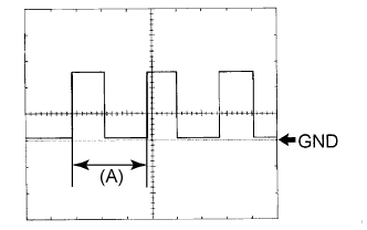
Waveform (Reference): Using an oscilloscope:
Item Condition Tool setting 5 V/DIV., 20 ms./DIV. Vehicle condition Driving at approx. 20 km/h (12 mph) Tech Tips
When the system is functioning normally, one wheel revolution generates 4 pulses. As the vehicle speed increases, the width indicated by (A) in the illustration narrows.
-
-
COMBINATION METER ASSEMBLY INNER CIRCUIT
-
Combination Meter Assembly Inner Circuit
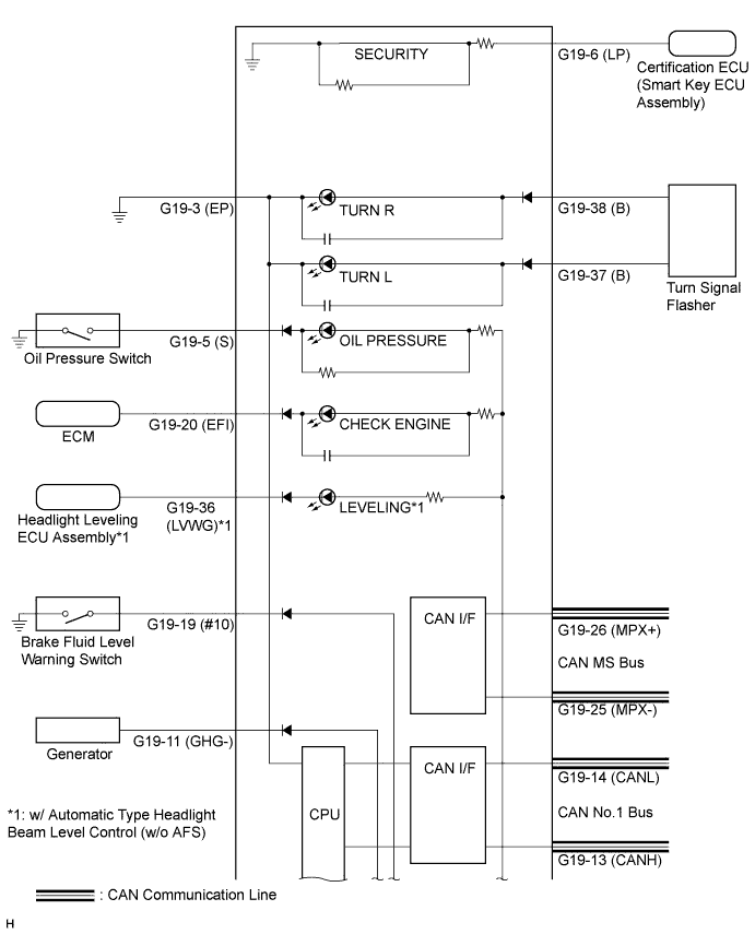
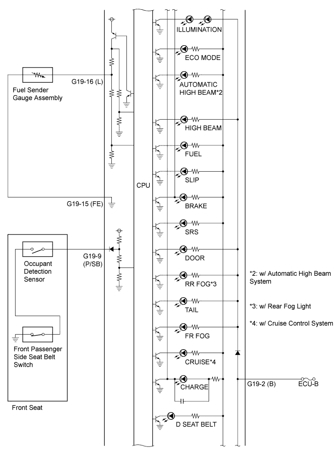
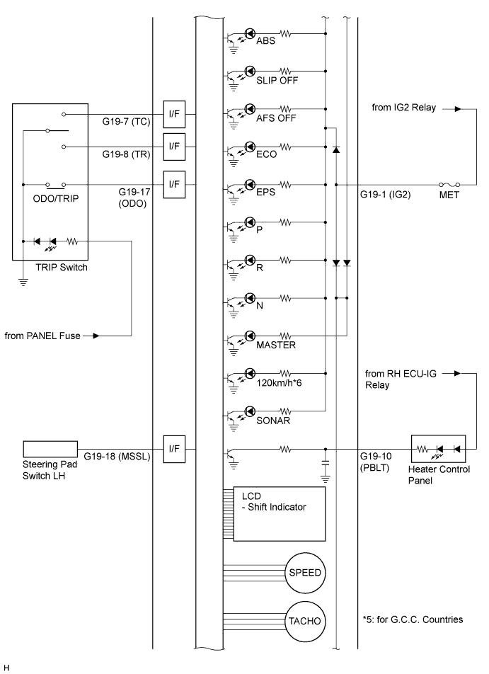
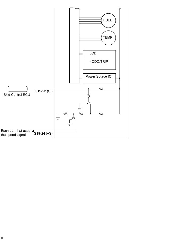
Terminal No. Wire Harness Side (Symbol) G19 1 MET Fuse (IG2) 2 ECU-B Fuse (B) 3 Ground (EP) 4 - 5 Oil Pressure Switch (S) 6 Certification ECU (Smart Key ECU Assembly) (LP) 7 Trip Switch (TC) 8 Trip Switch (TR) 9 Front Passenger Side Seat Belt Buckle Switch (P/SB) 10 Heater Control Panel (PBLT) 11 Generator (CHG-) 12 - 13 CAN Communication Line (CAN No. 1 Bus) (CANH) 14 CAN Communication Line (CAN No. 1 Bus) (CANL) 15 Fuel Sender Gauge Assembly (FE) 16 Fuel Sender Gauge Assembly (L) 17 Trip Switch (ODO) 18 Steering Pad Switch LH (MSSL) 19 Brake Fluid Level Warning Switch (#10) 20 ECM (EFI) 21 - 22 - 23 Skid Control ECU (SI) 24 Each part that uses the vehicle speed signal (+S) 25 CAN Communication Line (CAN MS Bus) (MPX-) 26 CAN Communication Line (CAN MS Bus) (MPX+) 27 - 28 - 29 - 30 - 31 - 32 - 33 - 34 - 35 - 36 Headlight Leveling ECU Assembly (LVWG)*1 37 Turn Signal Flasher (B) 38 Turn Signal Flasher (B) 39 - 40 -
-
*1: w/ Automatic Type Headlight Beam Level Control (w/o AFS)
-
-