METER / GAUGE SYSTEM SYSTEM DESCRIPTION

-
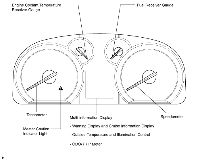
OUTLINE OF THE COMBINATION METER ASSEMBLY
-
Meter or Gauge
Item Detail Speedometer Indicates the vehicle speed based on a signal received from the skid control ECU. (CAN (CAN No. 1 Bus)) Tachometer Indicates the engine speed based on a signal received from the ECM. (CAN (CAN No. 1 Bus)) Fuel Receiver Gauge Indicates the fuel level based on a signal received from the fuel sender gauge assembly. (Direct Line) Engine Coolant Temperature Receiver Gauge Indicates the engine coolant temperature based on a signal received from the ECM. (CAN (CAN No. 1 Bus)) -
Warning or Indicator
Item Detail Beam Receives a beam indicator light signal from the main body ECU. (CAN (CAN No. 1 Bus)) Turn Receives a turn signal from the turn signal flasher. (Direct Line) Fuel Receives a fuel signal from the fuel sender gauge. (Direct Line) Brake Receives a brake signal from the brake fluid level warning switch (Direct Line) and the skid control ECU. (CAN (CAN No. 1 Bus)) SRS Receives an SRS signal from the center airbag sensor assembly. (CAN (CAN No. 1 Bus)) Open door Receives a door condition signal from the main body ECU. (CAN (CAN MS Bus)) Oil pressure Receives an oil pressure warning light signal from the oil pressure switch. (Direct Line) Charge Receives a charge indicator light signal from the generator (Direct Line) or ECM. (CAN (CAN No. 1 Bus)) MIL (Check engine warning light) Receives a MIL (check engine warning light) signal from the ECM. (Direct Line) Driver side seat belt Receives a driver side seat belt signal from the main body ECU. (CAN (CAN No. 1 Bus)) ABS Receives an ABS signal from the skid control ECU. (CAN (CAN No. 1 Bus)) EPS Receives an EPS signal from the power steering ECU. (CAN (CAN No. 1 Bus)) Front fog Receives a front fog indicator light signal from the main body ECU. (CAN (CAN No. 1 Bus)) Security Receives a security indicator light signal from the certification ECU (Smart key ECU assembly). (Direct Line) Tail Receives a indicator light signal from the main body ECU. (CAN (CAN No. 1 Bus)) Slip Receives a slip signal from the skid control ECU. (CAN (CAN No. 1 Bus)) VSC OFF Receives a VSC OFF signal from the skid control ECU. (CAN (CAN No. 1 Bus)) Cruise*5 Receives a cruise signal from the ECM. (CAN (CAN No. 1 Bus)) AFS OFF Receives an AFS OFF indicator light signal from the AFS ECU. (CAN (CAN No. 2 Bus)) Master caution indicator Comes on when the warning message appears on the multi-information display. ECO drive indicator Receives a vehicle speed signal from the skid control ECU (CAN (CAN No. 1 Bus)), shift position signal, engine speed signal, and current accelerator position signal from the ECM (CAN (CAN No. 1 Bus)) and illuminates when the vehicle is being driven economically. Clearance sonar Receives a clearance sonar indicator light signal from the clearance warning ECU. (CAN (CAN MS Bus)) Front passenger side seat belt Receives a front passenger side seat belt buckle switch signal from the front passenger side seat belt buckle switch (Direct Line) and transmits a front passenger side seat belt warning light signal to the heater control panel. (Direct Line) Shift Receives a shift condition signal from the park/neutral position switch and the ECM. (CAN (CAN No. 1 Bus)) Leveling*1 Receives a headlight leveling signal from the headlight leveling ECU assembly. (Direct Line) Speed limit*2 Receives a vehicle speed signal from the skid control ECU. (CAN (CAN No. 1 Bus)) Rear fog*3 Receives a rear fog indicator light signal from the main body ECU. (CAN (CAN No. 1 Bus)) Automatic high beam*4 Receives an automatic high beam indicator light (yellow) or (green) signal from the main body ECU. (CAN (CAN No. 1 Bus)) ECO mode Receives an ECO mode indicator light signal from the ECM. (CAN (CAN No. 1 Bus))
-
*1: w/ Automatic Type Headlight Beam Level Control (w/o AFS)
-
*2: for G.C.C. Countries
-
*3: w/ Rear Fog Light
-
*4: w/ Automatic High Beam System
-
*5: w/ Cruise Control System
-
-
-
MULTI-INFORMATION DISPLAY
Item Detail Cruise information display Average fuel consumption
-
Five types of information (average fuel consumption, average fuel consumption after refueling, current fuel consumption, driving range, and ECO zone display) can be displayed.
-
The ECO zone display will be displayed when all of the following conditions are met:
1) Engine switch is on (IG)
2) Shift lever is in D
The multi-information display is used to display the ECO zone display. The ECO zone display shows the current accelerator opening angle as a bar moving inside a box. The box on the left represents the recommended accelerator angle range for economical driving.
The meter CPU calculates the recommended accelerator opening angle range based on:
1) Accelerator opening angle
2) Vehicle speed
When the vehicle is driven with the ECO zone display bar in the recommended range, the ECO drive indicator light comes on to inform the driver that the vehicle is being driven in a manner that helps to achieve low fuel consumption*1. When the accelerator opening angle exceeds the recommended range, the meter CPU turns off the ECO drive indicator light and blinks the right side of the ECO zone display to inform the driver that the vehicle is not being driven economically.
In addition, when either of the following conditions is met, the meter CPU turns off the ECO drive indicator light and the ECO zone display:
1) The shift lever is in any position except D.
2) The vehicle is driven at speeds faster than 112 km/h (70 mph).
Average fuel consumption after refueling Current fuel consumption Driving range ECO zone display Warning display Each system warning Interrupts the multi-information display immediately when a warning occurs. Clearance sonar warning Displays the location of an obstacle and the approximate distance between the vehicle and the obstacle, and displays malfunction warning messages about sensor freezing or presence of dirt on the sensors. Outside temperature Displays the outside temperature. Illumination control Displays the current illumination level and adjust the combination meter assembly brightness. ODO/TRIP meter Indicates the driving distance.
-
*1: Since the update rates of the ECO drive indicator light and ECO zone display differ, there may be inconsistency between the operation of the ECO drive indicator light and ECO zone display. This does not indicate a malfunction.
-
-
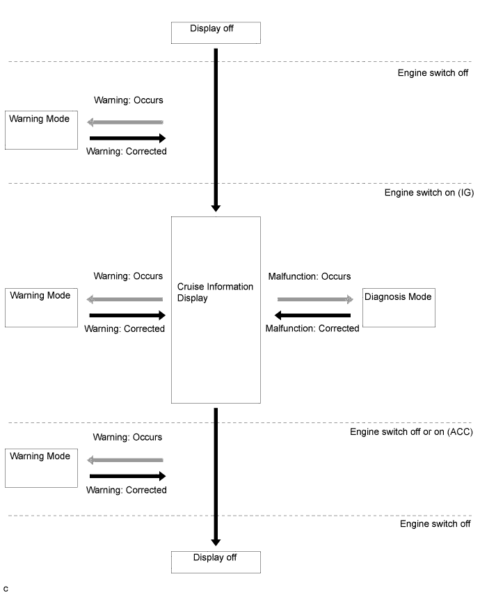
DISPLAY FLOW CHART
-
Display flow chart
-
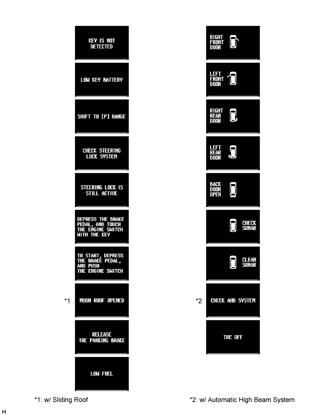
Each warning display
Tech Tips
Illustrations may differ from the actual screen displayed depending on the specifications of the vehicle.
-
-
LED INITIAL CHECK
-
Check the illumination function of the warning or indicator light listed below when the engine switch is turned on (IG).
-
*1: for G.C.C. Countries
-
-