LIGHTING SYSTEM Illumination Circuit
DESCRIPTION
The illuminated entry system receives signals from the ceiling light switches to control the ceiling lights.
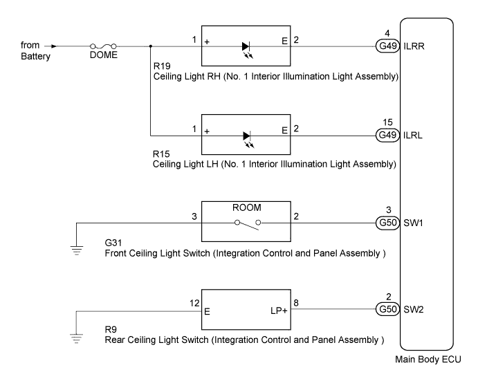
WIRING DIAGRAM
INSPECTION PROCEDURE
PROCEDURE
-
PERFORM ACTIVE TEST USING INTELLIGENT TESTER
-
Connect the intelligent tester to the DLC3.
-
Turn the engine switch on (IG).
-
Turn the intelligent tester on.
-
Enter the following menus: Body / Main Body / Active Test.
-
Check the operation.
Main Body Tester Display Test Part Control Range Diagnostic Note Ceiling Light Ceiling lights ON/OFF - OK Ceiling lights come on.
NG 
CHECK HARNESS AND CONNECTOR (BATTERY - MAIN BODY ECU) Click here
OK 
-
-
READ VALUE USING INTELLIGENT TESTER
-
Connect the intelligent tester to the DLC3.
-
Turn the engine switch on (IG).
-
Turn the intelligent tester on.
-
Enter the following menus: Body / Main Body / Data List.
-
Read the display on the intelligent tester.
Main Body Tester Display Measurement Item/Range Normal Condition Diagnostic Note Ceiling Light SW Front ceiling light switch /ON or OFF ON: Front ceiling light switch pushed
OFF: Front ceiling light switch not pushed
- OK Normal conditions listed above are displayed.
NG
INSPECT FRONT CEILING LIGHT SWITCH (INTEGRATION CONTROL AND PANEL ASSEMBLY) Click here
OK
-
-
READ VALUE USING INTELLIGENT TESTER
-
Connect the intelligent tester to the DLC3.
-
Turn the engine switch on (IG).
-
Turn the intelligent tester on.
-
Enter the following menus: Body / Main Body / Data List.
-
Read the display on the intelligent tester.
Main Body Tester Display Measurement Item/Range Normal Condition Diagnostic Note Rear Ceiling Light SW Rear ceiling light switch /ON or OFF ON: Rear ceiling light switch pushed
OFF: Rear ceiling light switch not pushed
- OK Normal conditions listed above are displayed.
NG
INSPECT REAR CEILING LIGHT SWITCH (INTEGRATION CONTROL AND PANEL ASSEMBLY) Click here
OK 
PROCEED TO NEXT SUSPECTED AREA SHOWN IN PROBLEM SYMPTOMS TABLE Click here
-
-
INSPECT FRONT CEILING LIGHT SWITCH (INTEGRATION CONTROL AND PANEL ASSEMBLY)
-
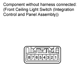
Remove the front ceiling light switch (integration control and panel assembly) Click here.
-
Measure the resistance according to the value(s) in the table below.
Standard Resistance Tester Connection Switch Condition Specified Condition 2 - 3 Front ceiling light switch not pushed 10 kΩ or higher Front ceiling light switch pushed Below 1 Ω
NG 
REPLACE FRONT CEILING LIGHT SWITCH (INTEGRATION CONTROL AND PANEL ASSEMBLY) Click here
OK
-
-
CHECK HARNESS AND CONNECTOR (FRONT CEILING LIGHT SWITCH - MAIN BODY ECU AND BODY GROUND)
-
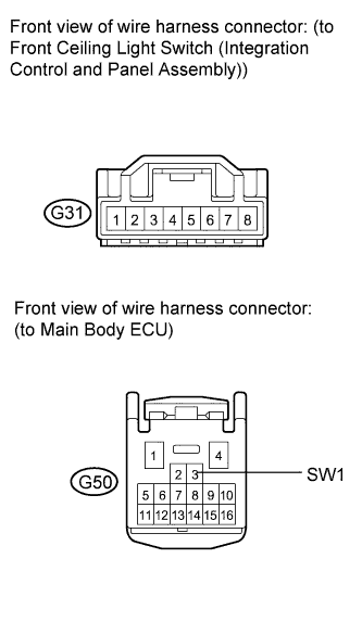
Disconnect the G50 main body ECU connector.
-
Disconnect the G31 integration control and panel assembly connector.
-
Measure the resistance according to the value(s) in the table below.
Standard Resistance Tester Connection Condition Specified Condition G50-3 (SW1) - G31-2 Always Below 1 Ω G50-3 (SW1) - Body ground Always 10 kΩ or higher G31-3 - Body ground Always Below 1 Ω
NG
REPAIR OR REPLACE HARNESS OR CONNECTOR
OK
REPLACE MAIN BODY ECU Click here
-
-
INSPECT REAR CEILING LIGHT SWITCH (INTEGRATION CONTROL AND PANEL ASSEMBLY)
-
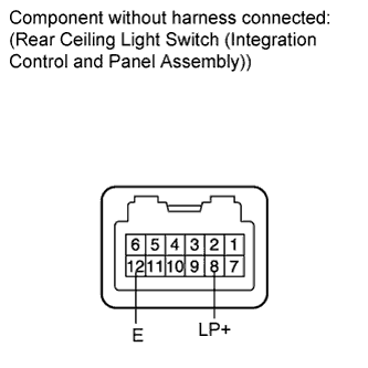
Remove the rear ceiling light switch (integration control and panel assembly) Click here.
-
Measure the resistance according to the value(s) in the table below.
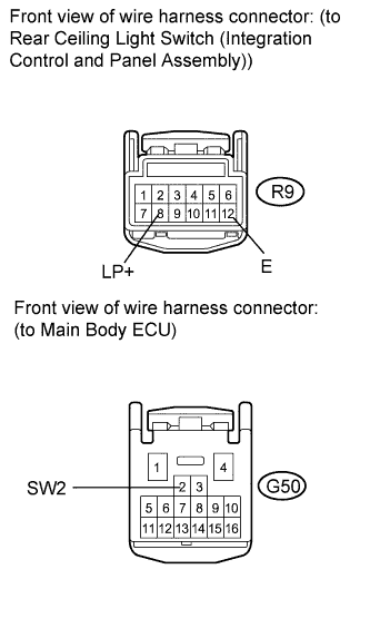
Standard Resistance Tester Connection Switch Condition Specified Condition 8 (LP+) - 12 (E) Rear ceiling light switch not pushed 10 kΩ or higher Rear ceiling light switch pushed Below 1 Ω
NG
REPLACE REAR CEILING LIGHT SWITCH (INTEGRATION CONTROL AND PANEL ASSEMBLY) Click here
OK
-
-
CHECK HARNESS AND CONNECTOR (REAR CEILING LIGHT SWITCH - MAIN BODY ECU AND BODY GROUND)
-
Disconnect the G50 main body ECU connector.
-
Disconnect the R9 integration control and panel assembly connector.
-
Measure the resistance according to the value(s) in the table below.
Standard Resistance Tester Connection Condition Specified Condition G50-2 (SW2) - R9-8 (LP+) Always Below 1 Ω G50-2 (SW2) - Body ground Always 10 kΩ or higher R9-12 (E) - Body ground Always Below 1 Ω
NG
REPAIR OR REPLACE HARNESS OR CONNECTOR
OK
REPLACE MAIN BODY ECU Click here
-
-
CHECK HARNESS AND CONNECTOR (BATTERY - MAIN BODY ECU)
-
Disconnect the G49 main body ECU connector.
-
Measure the voltage according to the value(s) in the table below.
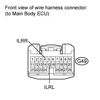
Standard Voltage Tester Connection Condition Specified Condition G49-4 (ILRR) - Body ground Always 11 to 14 V G49-15 (ILRL) - Body ground Always 11 to 14 V
NG
REPAIR OR REPLACE HARNESS OR CONNECTOR
OK
REPLACE MAIN BODY ECU Click here
-