LIGHTING SYSTEM Engine Switch Illumination Circuit
DESCRIPTION
When either of the following conditions is met, the engine switch illumination comes on.
-
The light control switch is in the TAIL position.
-
The interior light is turned on by the illuminated entry system.
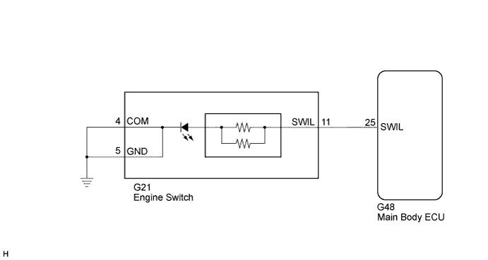
WIRING DIAGRAM
INSPECTION PROCEDURE
PROCEDURE
-
PERFORM ACTIVE TEST USING INTELLIGENT TESTER
-
Connect the intelligent tester to the DLC3.
-
Turn the engine switch on (IG).
-
Turn the intelligent tester on.
-
Enter the following menus: Body / Main Body / Active Test.
-
Check the operation.
Main Body Tester Display Test Part Control Range Diagnostic Note Indicator for Lighting Engine switch illumination ON/OFF All doors are closed. OK Engine switch illumination comes on.
NG 
INSPECT ENGINE SWITCH Click here
OK 
PROCEED TO NEXT SUSPECTED AREA SHOWN IN PROBLEM SYMPTOMS TABLE Click here
-
-
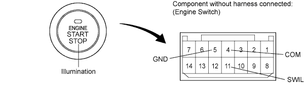
INSPECT ENGINE SWITCH
-
Remove the engine switch Click here for 2GR-FE, Click here for 2AZ-FE).
-
Connect a positive (+) lead from the battery to terminal 11 and a negative (-) lead to terminal 4 or 5.
-
Check that the illumination comes on.
OK Engine switch illumination comes on. Result Result Proceed to OK A NG (for 2GR-FE) B NG (for 2AZ-FE) C
B 
REPLACE ENGINE SWITCH (for 2GR-FE) Click here
C
REPLACE ENGINE SWITCH (for 2AZ-FE) Click here
A 
-
-
CHECK HARNESS OR CONNECTOR (ENGINE SWITCH - MAIN BODY ECU AND BODY GROUND)
-
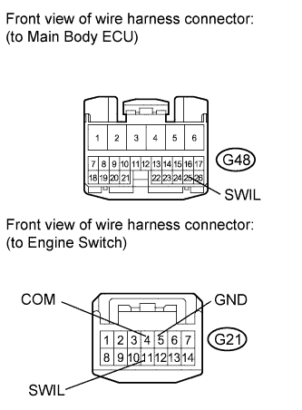
Disconnect the G48 main body ECU connector.
-
Disconnect the G21 engine switch connector.
-
Measure the resistance according to the value(s) in the table below.
Standard Resistance Tester Connection Condition Specified Condition G21-11 (SWIL) - G48-25 (SWIL) Always Below 1 Ω G21-4 (COM) or G21-5 (GND) - Body ground Always Below 1 Ω G48-25 (SWIL) - Body ground Always 10 kΩ or higher
NG
REPAIR OR REPLACE HARNESS OR CONNECTOR
OK
REPLACE MAIN BODY ECU Click here
-