DESCRIPTION
The back door motor unit (power back door ECU) receives a signal from the back door courtesy switch to control the luggage compartment light.
INSPECTION PROCEDURE
PROCEDURE
- Click here
READ VALUE USING INTELLIGENT TESTER
-
Connect the intelligent tester to the DLC3.
-
Turn the engine switch on (IG).
-
Turn the intelligent tester on.
-
Enter the following menus: Body / Back Door / Data List.
-
Read the display on the intelligent tester.
Table 1. Back Door Tester Display Measurement Item/Range Normal Condition Diagnostic Note Back door Courtesy SW Back door Courtesy switch signal/ON or OFF ON: Back door open
OFF: Back door closed
- OK Normal conditions listed above are displayed.
- OKClick here
- NGClick here
-
- Click here
INSPECT NO. 1 LUGGAGE COMPARTMENT LIGHT ASSEMBLY
-
Inspect No. 1 luggage compartment light assembly (Click here).
OK No. 1 Luggage compartment light assembly is normal.
- OKClick here
- NGClick here
-
- Click here
CHECK HARNESS AND CONNECTOR (BATTERY - BACK DOOR MOTOR UNIT (POWER BACK DOOR ECU))
-
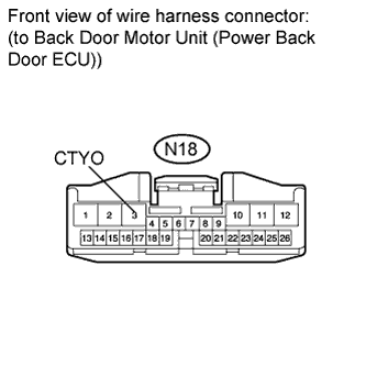
Disconnect the N18 back door motor unit (power back door ECU) connector.
-
Measure the voltage according to the value(s) in the table below.
Standard Voltage Tester connection Switch Condition Specified condition N18-3 (CTYO) - Body ground Luggage compartment light switch off Below 1 V N18-3 (CTYO) - Body ground Luggage compartment light switch on 11 to 14 V
- OKClick here
- NGClick here
-
- Click here
INSPECT BACK DOOR COURTESY SWITCH (BACK DOOR LOCK ASSEMBLY)
-
Inspect back door courtesy switch (back door lock assembly) (Click here).
OK Back door courtesy switch (back door lock assembly) is normal.
- OKClick here
- NGClick here
-
- Click here
CHECK HARNESS AND CONNECTOR (BACK DOOR LOCK ASSEMBLY - ECU AND BODY GROUND)
-
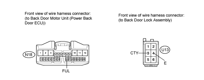
Disconnect the N18 back door motor unit (power back door ECU) connector.
-
Disconnect the U13 back door lock assembly connector.
-
Measure the resistance according to the value(s) in the table below.
Standard Resistance Tester Connection Condition Specified Condition N18-20 (FUL) - U13-3 (CTY) Always Below 1 Ω N18-20 (FUL) - Body ground Always 10 kΩ or higher U13-4 (E) - Body ground Always Below 1 Ω
- OKClick here
- NGClick here
-
- Click here
REPAIR OR REPLACE HARNESS OR CONNECTOR
- Click here
REPLACE BACK DOOR MOTOR UNIT (POWER BACK DOOR ECU)Click here
- Click here
REPLACE BACK DOOR COURTESY SWITCH (BACK DOOR LOCK ASSEMBLY)Click here
- Click here
REPLACE NO. 1 LUGGAGE COMPARTMENT LIGHT ASSEMBLYClick here