LIGHTING SYSTEM Footwell Light Circuit
DESCRIPTION
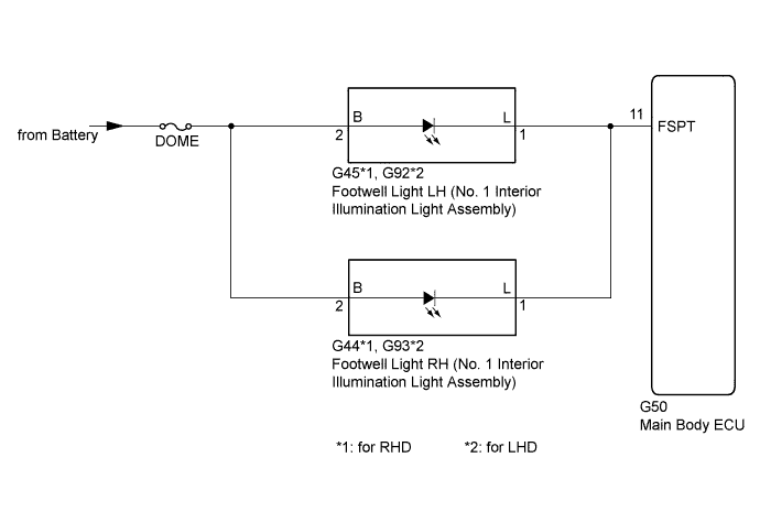
The main body ECU receives information regarding the door lock position switches, door courtesy switches and engine switch to control the footwell lights.
WIRING DIAGRAM
INSPECTION PROCEDURE
PROCEDURE
-
PERFORM ACTIVE TEST USING INTELLIGENT TESTER
-
Connect the intelligent tester to the DLC3.
-
Turn the engine switch on (IG).
-
Turn the intelligent tester on.
-
Enter the following menus: Body / Main Body / Active Test.
-
Check the operation.
Main Body Tester Display Test Part Control Range Diagnostic Note Step Light Operation Footwell light LH and RH ON/OFF - OK Footwell lights come on.
NG 
CHECK HARNESS AND CONNECTOR (MAIN BODY ECU - BATTERY) Click here
OK 
PROCEED TO NEXT SUSPECTED AREA SHOWN IN PROBLEM SYMPTOMS TABLE Click here
-
-
CHECK HARNESS AND CONNECTOR (MAIN BODY ECU - BATTERY)
-
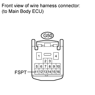
Disconnect the G50 main body ECU connector.
-
Measure the voltage according to the value(s) in the table.
Standard Voltage Tester Connection Condition Specified Condition G50-11 (FSPT) - Body ground Always 11 to 14 V
NG 
REPAIR OR REPLACE HARNESS OR CONNECTOR
OK
REPLACE MAIN BODY ECU Click here
-