DESCRIPTION
-
The main body ECU receives the IG signal to control the illuminated entry system.
-
The main body ECU receives the IG signal to control the automatic light control system and light turn-off system.
INSPECTION PROCEDURE
PROCEDURE
- Click here
INSPECT SMART ENTRY AND START SYSTEM (POWER SOURCE MODE)
Tip:OK Power source mode operates normally.
- OKClick here
- NGClick here
- Click here
READ VALUE USING INTELLIGENT TESTER
-
Connect the intelligent tester to the DLC3.
-
Turn the engine switch on (IG).
-
Turn the intelligent tester on.
-
Enter the following menus: Body / Main Body / Data List.
-
Read the display on the intelligent tester.
Table 1. Main Body Tester Display Measurement Item/Range Normal Condition Diagnostic Note IG SW Engine switch IG signal / ON or OFF ON: Engine switch on (IG)
OFF: Engine switch off
- OK Normal conditions listed above are displayed.
- OKClick here
- NGClick here
-
- Click here
INSPECT FUSE (LH ECU-IG)
-
Remove the LH ECU-IG fuse from the instrument panel junction block LH.
-
Measure the resistance according to the value(s) in the table below.
Standard Resistance Tester Connection Condition Specified Condition LH ECU-IG Always Below 1 Ω
- OKClick here
- NGClick here
-
- Click here
CHECK HARNESS AND CONNECTOR (BATTERY - MAIN BODY ECU)
-
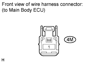
Disconnect the 4M main body ECU connector.
-
Measure the voltage according to the value(s) in the table below.
Standard Voltage Tester Connection Condition Specified Condition 4M-1 - Body ground Always 11 to 14 V
- OKClick here
- NGClick here
-
- Click here
CHECK HARNESS AND CONNECTOR (MAIN BODY ECU - BODY GROUND)
-
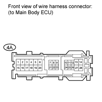
Disconnect the 4A main body ECU connector.
-
Measure the resistance according to the value(s) in the table below.
Standard Resistance Tester Connection Condition Specified Condition 4A-5 - Body ground Always Below 1 Ω
- OKClick here
- NGClick here
-
- Click here
CHECK HARNESS AND CONNECTOR (MAIN BODY ECU CONNECTOR G48 - MAIN BODY ECU CONNECTOR 4D)
-
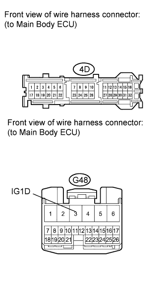
Disconnect the G48 main body ECU connector.
-
Disconnect the 4D main body ECU connector.
-
Measure the resistance according to the value(s) in the table below.
Standard Resistance Tester Connection Condition Specified Condition 4D-11 - G48-3 (IG1D) Always Below 1 Ω 4D-11 - Body ground Always 10 kΩ or higher
- OKClick here
- NGClick here
-
- Click here
REPAIR OR REPLACE HARNESS OR CONNECTOR
- Click here
PROCEED TO NEXT SUSPECTED AREA SHOWN IN PROBLEM SYMPTOMS TABLEClick here
- Click here
REPLACE FUSE
- Click here
REPLACE MAIN BODY ECUClick here
- Click here
GO TO SMART ENTRY AND START SYSTEMClick here