LIGHTING SYSTEM TERMINALS OF ECU

-
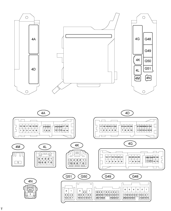
CHECK MAIN BODY ECU (PASSENGER SIDE JUNCTION BLOCK ASSEMBLY)
-
Disconnect the G50, 4A and 4K ECU connectors.
-
Measure the resistance according to the value(s) in the table below.
Standard Resistance Terminal No. (Symbol) Wiring Color Terminal Description Condition Specified Condition G50-1 (GND) - Body ground W-B - Body ground Ground Always Below 1 Ω 4A-3 (GND2) - Body ground W-B - Body ground Ground Always Below 1 Ω If the result is not as specified, there may be a malfunction in the wire harness.
-
Measure the voltage according to the value(s) in the table below.
Standard Voltage Terminal No. (Symbol) Wiring Color Terminal Description Condition Specified Condition 4A-26 (ACC) - Body ground GR - Body ground ACC power supply Engine switch on (ACC) 11 to 14 V Engine switch off Below 1 V 4K-9 (BATB) - Body ground W - Body ground Battery power supply Always 11 to 14 V If the result is not as specified, there may be a malfunction in the wire harness.
-
Reconnect the G50, 4A and 4K ECU connectors.
-
Measure the voltage and check for pulses according to the value(s) in the table below.
Standard Voltage Terminal No. (Symbol) Wiring Color Terminal Description Condition Specified Condition G48-9 (LSWD) - Body ground SB - Body ground Driver door unlock detection switch input Driver door locked Pulse generation Driver door unlocked Below 1 V G48-24 (DCTY) - Body ground W - Body ground Driver door courtesy switch input Driver door closed 11 to 14 V Driver door open Below 1 V G49-4 (ILRR) - Body ground R - Body ground Ceiling light RH drive output Ceiling light RH on (100% brightness of light on state) Below 1.5 V Ceiling light RH on (Illuminate in light adjustment state) Pulse generation Ceiling light RH off 11 to 14 V G49-5 (LSWR) - Body ground Y - Body ground Slide door RH unlock detection switch input Slide door RH locked Pulse generation Slide door RH unlocked Below 1 V G49-7 (RCTY) - Body ground LG - Body ground Slide door RH courtesy switch input Slide door RH closed Pulse generation Slide door RH open Below 1 V G49-15 (ILRL) - Body ground L - Body ground Ceiling light LH drive output Ceiling light LH on (100% brightness of light on state) Below 1.5 V Ceiling light LH on (Illuminate in light adjustment state) Pulse generation Ceiling light LH off 11 to 14 V G49-21 (PCTY) - Body ground L - Body ground Front passenger door courtesy switch input Front passenger door closed 11 to 14 V Front passenger door open Below 1 V G49-25 (BCTY) - Body ground W - Body ground Back door courtesy switch input Back door closed and luggage compartment light switch on (*1, *3) 11 to 14 V Back door closed and luggage compartment light switch off (*1, *3) Pulse generation Back door closed (*2, *4) Pulse generation Back door open Below 1 V G50-2 (SW2) - Body ground L - Body ground Rear ceiling light switch input Rear ceiling light switch not pushed 11 to 14 V Rear ceiling light switch pushed Below 1 V G50-3 (SW1) - Body ground SB - Body ground Front ceiling light switch input Front ceiling light switch not pushed 11 to 14 V Front ceiling light switch pushed Below 1 V G50-11 (FSPT) - Body ground G - Body ground Footwell light drive output Footwell light on and shift lever in P Below 1 V Footwell light on and shift lever not in P Pulse generation Footwell light off 10 to 14 V 4A-4 (LCTY) - Body ground R- Body ground Slide door LH courtesy switch input Slide door LH closed Pulse generation Slide door LH open Below 1 V 4D-2 (ILE) - Body ground W - Body ground Interior light drive output Interior light on Below 1 V Interior light off 11 to 14 V 4D-6 (LSWL) - Body ground SB - Body ground Slide door LH unlock detection switch input Slide door LH locked Pulse generation Slide door LH unlocked Below 1 V Tech Tips
-
*1: w/o Power Back Door System
-
*2: w/ Power Back Door System
-
*3: w/o Back Door Closer System
-
*4: w/ Back Door Closer System
If the result is not as specified, the ECU may have a malfunction.
-
-
-
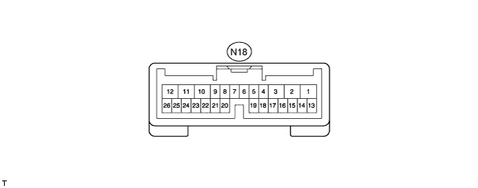
CHECK BACK DOOR MOTOR UNIT (POWER BACK DOOR ECU)
-
Disconnect the N18 ECU connector.
-
Measure the resistance according to the value(s) in the table below.
Standard Resistance Terminal No. (Symbol) Wiring Color Terminal Description Condition Specified Condition N18-11 (GND) - Body ground W-B - Body ground Ground Always Below 1 Ω If the result is not as specified, there may be a malfunction on the wire harness side.
-
Measure the voltage according to the value(s) in the table below.
Standard Voltage Terminal No. (Symbol) Wiring Color Terminal Description Condition Specified Condition N18-10 (ECUB) - Body ground R - Body ground Battery power supply Always 11 to 14 V N18-12 (B) - Body ground B - Body ground Battery power supply Always 11 to 14 V N18-8 (IG) - Body ground R - Body ground IG power supply Engine switch on (IG) 11 to 14 V Engine switch off Below 1 V If the result is not as specified, there may be a malfunction on the wire harness side.
-
Reconnect the N18 ECU connector.
-
Initialize the power back door system Click here.
-
Measure the voltage and check for pulses according to the value(s) in the table below.
Standard Voltage Terminal No. (Symbol) Wiring Color Terminal Description Condition Specified Condition N18-3 (CTYO) - Body ground W - Body ground Luggage compartment light drive output Luggage compartment light on Below 1 V Luggage compartment light off 11 to 14 V N18-20 (FUL) - Body ground W - Body ground Back door courtesy switch signal input Back door open Below 1 V Back door closed Pulse generation Tech Tips
If the result is not as specified, the ECU may have a malfunction.
-
-
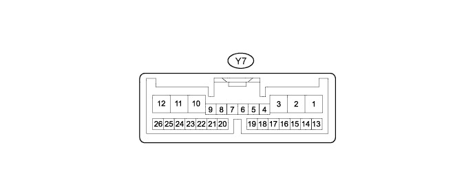
CHECK REAR SEAT CLIMATE CONTROL ECU LH
-
Disconnect the Y7 ECU connector.
-
Measure the resistance according to the value(s) in the table below.
Standard Resistance Terminal No. (Symbol) Wiring Color Terminal Description Condition Specified Condition Y7-3 (GND) - Body ground W-B - Body ground Ground Always Below 1 Ω If the result is not as specified, there may be a malfunction on the wire harness side.
-
Measure the voltage according to the value(s) in the table below.
Standard Voltage Terminal No. (Symbol) Wiring Color Terminal Description Condition Specified Condition Y7-13 (+B) - Body ground R - Body ground Battery power supply Always 11 to 14 V Y7-12 (IG) - Body ground P - Body ground IG power supply Engine switch on (IG) 11 to 14 V Engine switch off Below 1 V If the result is not as specified, there may be a malfunction on the wire harness side.
-
Reconnect the Y7 ECU connector.
-
Measure the voltage and check for pulses according to the value(s) in the table below.
Standard Voltage Terminal No. (Symbol) Wiring Color Terminal Description Condition Specified Condition Y7-9 (RSWM) - Body ground R - Body ground Reading light ON/OFF switch (for LH Side) signal input Reading light ON/OFF switch (for LH Side) pushed in Below 1 V Reading light ON/OFF switch (for LH Side) not pushed 11 to 14 V Y7-22 (RSWU) - Body ground W - Body ground Reading light dimmer switch (+) (for LH Side) signal input Reading light dimmer switch (+) (for LH Side) pushed in Below 1 V Reading light dimmer switch (+) (for LH Side) not pushed 11 to 14 V Y7-22 (RSWD) - Body ground B - Body ground Reading light dimmer switch (-) (for LH Side) signal input Reading light dimmer switch (-) (for LH Side) pushed in Below 1 V Reading light dimmer switch (-) (for LH Side) not pushed 11 to 14 V Y7-25 (RDLP) - Body ground Y - Body ground Reading light LH (spot light assembly LH) drive output Reading light LH (spot light assembly LH) on (100% brightness of light on state) Below 1 V Reading light LH (spot light assembly LH) on (Illuminate in light adjustment state) Pulse generation Reading light LH (spot light assembly LH) off 11 to 14 V Tech Tips
If the result is not as specified, the ECU may have a malfunction.
-
-
CHECK REAR SEAT CLIMATE CONTROL ECU RH

-
Disconnect the X7 ECU connector.
-
Measure the resistance according to the value(s) in the table below.
Standard Resistance Terminal No. (Symbol) Wiring Color Terminal Description Condition Specified Condition X7-3 (GND) - Body ground W-B - Body ground Ground Always Below 1 Ω If the result is not as specified, there may be a malfunction on the wire harness side.
-
Measure the voltage according to the value(s) in the table below.
Standard Voltage Terminal No. (Symbol) Wiring Color Terminal Description Condition Specified Condition X7-13 (+B) - Body ground R - Body ground Battery power supply Always 11 to 14 V X7-12 (IG) - Body ground P - Body ground IG power supply Engine switch on (IG) 11 to 14 V Engine switch off Below 1 V If the result is not as specified, there may be a malfunction on the wire harness side.
-
Reconnect the X7 ECU connector.
-
Measure the voltage and check for pulses according to the value(s) in the table below.
Standard Voltage Terminal No. (Symbol) Wiring Color Terminal Description Condition Specified Condition X7-9 (RSWM) - Body ground R - Body ground Reading light ON/OFF switch (for RH Side) signal input Reading light ON/OFF switch (for RH Side) pushed in Below 1 V Reading light ON/OFF switch (for RH Side) not pushed 11 to 14 V X7-22 (RSWU) - Body ground W - Body ground Reading light dimmer switch (+) (for RH Side) signal input Reading light dimmer switch (+) (for RH Side) pushed in Below 1 V Reading light dimmer switch (+) (for RH Side) not pushed 11 to 14 V X7-22 (RSWD) - Body ground B - Body ground Reading light dimmer switch (-) (for RH Side) signal input Reading light dimmer switch (-) (for RH Side) pushed in Below 1 V Reading light dimmer switch (-) (for RH Side) not pushed 11 to 14 V X7-25 (RDLP) - Body ground Y - Body ground Reading light RH (spot light assembly RH) drive output Reading light RH (spot light assembly RH) on (100% brightness of light on state) Below 1 V Reading light RH (spot light assembly RH) on (Illuminate in light adjustment state) Pulse generation Reading light RH (spot light assembly RH) off 11 to 14 V Tech Tips
If the result is not as specified, the ECU may have a malfunction.
-