ELECTRICAL KEY OSCILLATOR (for Front Floor) INSTALLATION

-
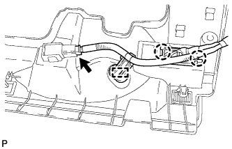
INSTALL ELECTRICAL KEY OSCILLATOR
-
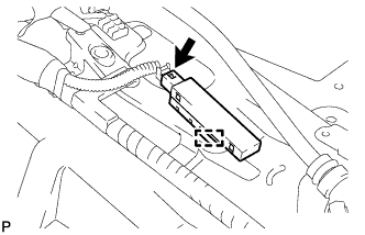
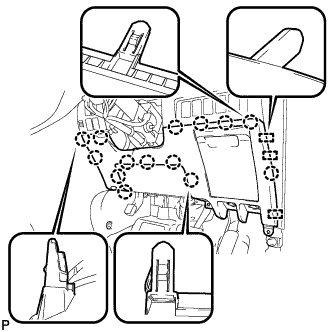
Engage the clamp to install the electrical key oscillator.
Note
Be careful when installing the electrical key oscillator. If the oscillator is dropped, replace it with a new one.
-
Connect the connector.
-
-
INSTALL FRONT FLOOR MAT PAD
-
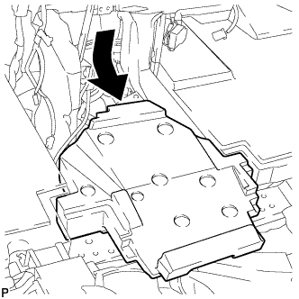
Install the front floor mat pad.
-
Install the floor carpet to the original position.
-
-
INSTALL INSTRUMENT CLUSTER FINISH PANEL ASSEMBLY
-
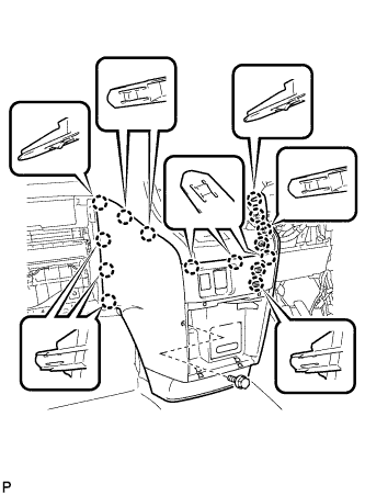
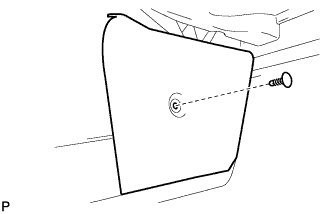
Engage the 15 claws.
Tech Tips
Before engaging the 15 claws, make sure that the claws are positioned correctly.
Note
Make sure that the claws are fully engaged.
-
Install the instrument cluster finish panel assembly with the bolt <C>.
-
-
INSTALL INSTRUMENT PANEL BOX ASSEMBLY
-
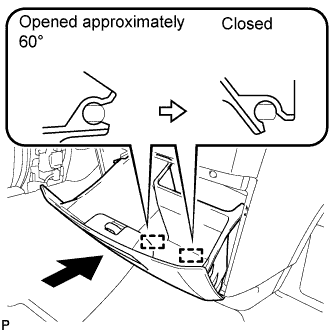
With the instrument panel box assembly opened approximately 60° from its closed position, engage the 2 hinges horizontally.
Note
Engaging the hinges from the top will deform the hinges. Be sure to install the instrument panel box assembly horizontally.
-
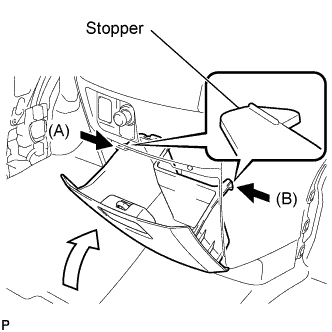
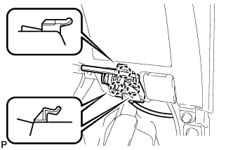
Slightly bend stoppers (A) and (B) in the directions indicated by the arrows in the illustration and engage the stoppers to install the instrument panel box assembly.
-
-
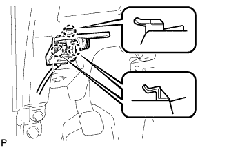
INSTALL GLOVE COMPARTMENT DOOR ASSEMBLY
-
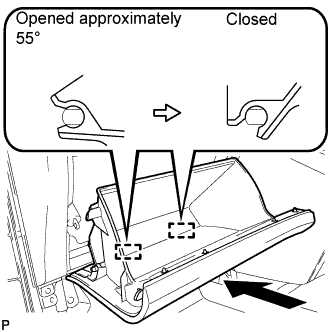
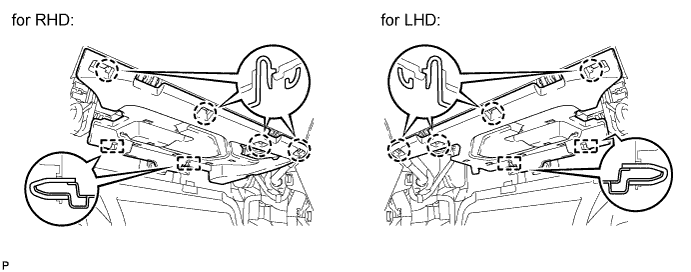
With the glove compartment door assembly opened approximately 55° from its closed position, engage the 2 hinges horizontally.
Note
Engaging the hinges from the top will deform the hinges. Be sure to install the glove compartment door assembly horizontally.
-
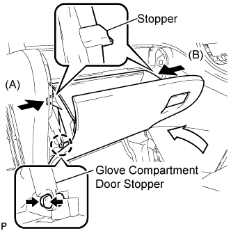
Slightly bend stoppers (A) and (B) in the directions indicated by the arrows in the illustration and engage the stoppers to install the glove compartment door assembly.
-
Engage the claw and connect the glove compartment door stopper.
-
-
INSTALL NO. 2 INSTRUMENT PANEL UNDER COVER SUB-ASSEMBLY
-
Connect the connector.
-
Engage the 2 guides.
-
Engage the 4 claws to install the No. 2 instrument panel under cover sub-assembly.
Note
Make sure that the claws are fully engaged.
-
-
INSTALL CENTER FLOOR CARPET COVER LH
-
Engage the 4 claws.
-

Install the center floor carpet cover LH with the clip.
-
-
INSTALL CENTER FLOOR CARPET COVER RH (for RHD)
-
Engage the 4 claws.
-
Install the center floor carpet cover RH with the 2 clips.
-
-
INSTALL CENTER FLOOR CARPET COVER RH (for LHD)
-
Engage the 5 claws.
-
Install the center floor carpet cover RH with the clip.
-
-
INSTALL LOWER INSTRUMENT PANEL FINISH PANEL (for RHD)
-
Engage the 3 guides and 14 claws.
Tech Tips
Make sure that all claws around the entire circumference of the driver side knee airbag assembly are fully engaged.
Note
Make sure that the claws are fully engaged.
-
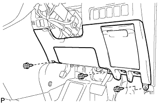
Install the lower instrument panel finish panel with the 3 screws <B>.
-

Engage the 3 claws and the fuel lid lock control cable assembly.
-
Engage the 3 claws and the hood lock control cable assembly.
-
-
INSTALL LOWER INSTRUMENT PANEL FINISH PANEL (for LHD)
-
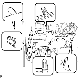
Engage the 3 guides, 13 claws and clip.
Tech Tips
Make sure that all claws around the entire circumference of the driver side knee airbag assembly are fully engaged.
Note
Make sure that the claws are fully engaged.
-
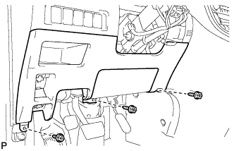
Install the lower instrument panel finish panel with the 3 screws <B>.
-

Connect the fuel filler opening lid lock sub-assembly to the fuel lid lock open lever sub-assembly.
-
Engage the 3 claws and the fuel lid lock control cable assembly.
-

Engage the 3 claws and the hood lock control cable assembly.
-
-
INSTALL NO. 1 INSTRUMENT PANEL UNDER COVER SUB-ASSEMBLY (for RHD)
-
Engage the 2 claws and DLC3.
-
Engage the clamp.
-
Connect the connector.
-

Engage the 2 claws and 2 guides.
Note
Make sure that the claws are fully engaged.
-
Install the No. 1 instrument panel under cover sub-assembly with the 2 screws <B>.
-
-
INSTALL NO. 1 INSTRUMENT PANEL UNDER COVER SUB-ASSEMBLY (for LHD)
-
Engage the clamp.
-
Connect each connector.
-

Engage the 2 claws and guide.
Note
Make sure that the claws are fully engaged.
-
Install the No. 1 instrument panel under cover sub-assembly with the 2 screws <B>.
-
-
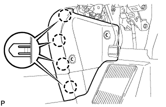
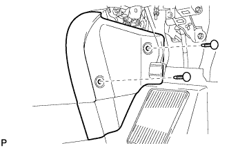
INSTALL DOOR SCUFF PLATE ASSEMBLY RH
-
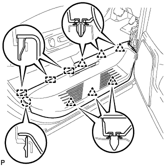
Engage the 3 guides, claw and 6 clips to install the door scuff plate assembly RH.
-
-
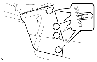
INSTALL COWL SIDE TRIM BOARD RH (for RHD)
-

Engage the 2 guides, claw and clip to install the cowl side trim board RH.
-
Install the clip(A).
-
-
INSTALL COWL SIDE TRIM BOARD RH (for LHD)
-
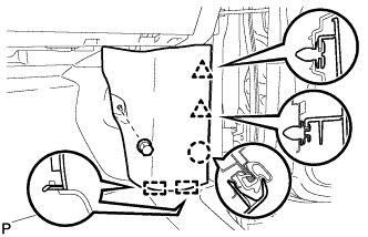
Engage the 2 guides, claw and the 2 clips to install the cowl side trim board RH.
-
Install the clip(A).
-
-
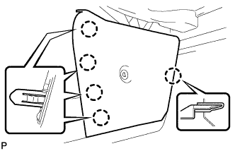
INSTALL DOOR SCUFF PLATE ASSEMBLY LH
Tech Tips
Use the same procedure for the LH side and RH side.
-
INSTALL COWL SIDE TRIM BOARD LH (for RHD)
-
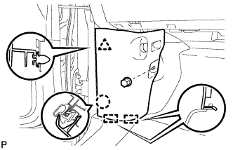
Engage the 2 guides, claw and clip to install the cowl side trim board LH.
-
Install the clip(A).
-
-
INSTALL COWL SIDE TRIM BOARD LH (for LHD)
-
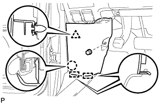
Engage the 2 guides, claw and clip to install the cowl side trim board LH.
-
Install the clip(A).
-