THEFT DETERRENT SYSTEM TERMINALS OF ECU

-
CHECK CERTIFICATION ECU (SMART KEY ECU ASSEMBLY)
-
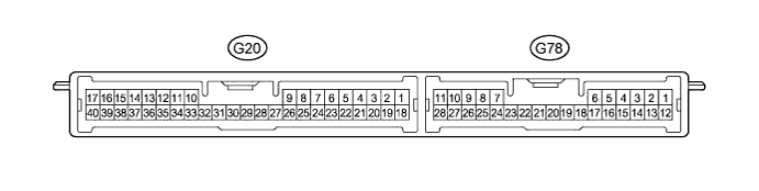
Disconnect the G20 and G78 certification ECU (smart key ECU assembly) connectors.
-
Measure the voltage and resistance according to the value(s) in the table below.
Tech Tips
Measure the values on the wire harness side with the connectors disconnected.
Tester Connection Wiring Color Terminal Description Condition Specified Condition G20-1 (+B) - Body ground R - Body ground +B power supply Always 11 to 14 V G20-17 (E) - Body ground W-B - Body ground Ground Always Below 1 Ω G78-24 (HSW) - Body ground LG - Body ground Engine hood courtesy switch Engine hood open (OFF) → closed (ON) 10 kΩ or higher → Below 1 Ω If the result is not as specified, there may be a malfunction in the wire harness.
-
Reconnect the G20 and G78 certification ECU (smart key ECU assembly) connectors.
-
Measure the voltage according to the value(s) in the table below.
Tester Connection Wiring Color Terminal Description Condition Specified Condition G20-2 (IND) - Body ground V - Body ground Security indicator output Security indicator on (It comes on only in arming preparation state or alarm sounding state. It flashes when immobiliser is operating.) Below 1 V ← → 3 to 14 V G78-20 (SH-) - Body ground Y - Body ground Security horn drive output Security horn sounding (Theft deterrent system is in alarm sounding state) Below 1 V ← → 11 to 14 V If the result is not as specified, the certification ECU (smart key ECU assembly) may have a malfunction.
-
-
CHECK MAIN BODY ECU
-
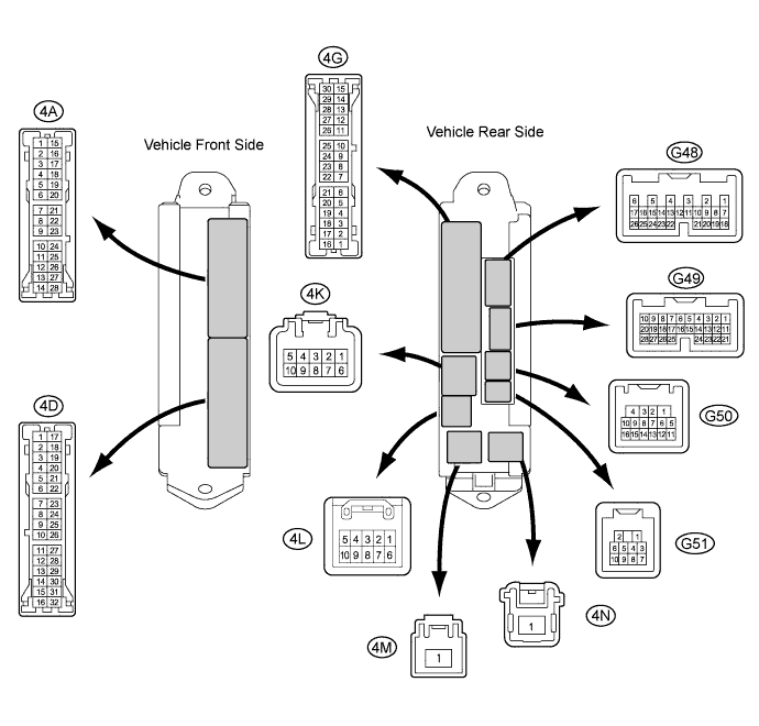
Disconnect the 4K, 4A, G48, G49 and G50 main body ECU connectors.
-
Measure the voltage and resistance according to the value(s) in the table below.
Tech Tips
Measure the values on the wire harness side with the connectors disconnected.
Tester Connection Wiring Color Terminal Description Condition Specified Condition 4A-26 (ACC) - Body ground GR - Body ground Ignition power supply (ACC signal) engine switch on (ACC) → off 11 to 14 V → Below 1 V 4M-1 (IG) - Body ground W - Body ground Ignition power supply (IG signal) engine switch on (IG) → off 11 to 14 V → Below 1 V 4M-1 (ALTB) - Body ground W - Body ground +B (power system alternator system) power supply engine switch off 11 to 14 V G50-1 (GND) - Body ground W-B - Body ground Ground Always Below 1 Ω 4A-3 (GND2) - Body ground W-B - Body ground Ground Always Below 1 Ω G48-24 (DCTY) - Body ground W - Body ground Driver side door courtesy light switch input Driver side door closed (OFF) → open (ON) 10 kΩ or higher → Below 1 Ω G49-21 (PCTY) - Body ground L - Body ground Passenger side courtesy light switch input Passenger side door closed (OFF) → open (ON) 10 kΩ or higher → Below 1 Ω 4A-4 (LCTY) - Body ground R - Body ground Rear courtesy light switch LH input Rear door LH closed (OFF) → open (ON) 10 kΩ or higher → Below 1 Ω G49-7 (RCTY) - Body ground LG - Body ground Rear courtesy light switch RH input Rear door RH closed (OFF) → open (ON) 10 kΩ or higher → Below 1 Ω G49-25 (BCTY) - Body ground W - Body ground Back door courtesy switch Back door closed (OFF) → open (ON) 10 kΩ or higher → Below 1 Ω If the result is not as specified, there may be a malfunction in the wire harness.
-
Reconnect the 4K, 4A, G48, G49 and G50 main body ECU connectors.
-
Measure the voltage according to the value(s) in the table below.
Tester Connection Wiring Color Terminal Description Condition Specified Condition 4D-1 (ACT+) - Body ground B - Body ground Door lock motor lock drive output (Driver door) Door control switch (Master switch) or driver door key cylinder off → lock → off Below 1 V → 11 to 14 V → Below 1 V 4D-5 (ACT+) - Body ground W - Body ground Door lock motor lock drive output (Front passenger door) Door control switch (Master switch) or driver door key cylinder off → lock → off Below 1 V → 11 to 14 V → Below 1 V 4G-7 (ACT+) - Body ground R - Body ground Door lock motor lock drive output (Rear door LH) Door control switch (Master switch) or driver door key cylinder off → lock → off Below 1 V → 11 to 14 V → Below 1 V 4D-4 (ACT+) - Body ground GR - Body ground Door lock motor lock drive output (Rear door RH) Door control switch (Master switch) or driver door key cylinder off → lock → off Below 1 V → 11 to 14 V → Below 1 V 4D-6 (LSWL) - Body ground SB - Body ground Rear left lock position switch input Rear left door unlock → lock Below 1 V → 11 to 14 V or pulse generation G49-5 (LSWR) - Body ground Y - Body ground Rear right door lock position switch input Rear right door unlock → lock Below 1 V → 11 to 14 V or pulse generation G49-27 (LSWP) - Body ground R - Body ground Front passenger door lock position switch input Front passenger door unlock → lock Below 1 V → 11 to 14 V or pulse generation G48-9 (LSWD) - Body ground SB- Body ground Driver door lock position switch input Driver door unlock → lock Below 1 V → 11 to 14 V or pulse generation G50-4 (HAZ) - Body ground GR - Body ground Turn signal flasher relay signal System in alarm sounding state Below 1 V ← → 11 to 14 V 4K-2 (HORN) - Body ground Y - Body ground Vehicle horn drive output Vehicle horns sounding
(Theft deterrent system is in alarm sounding state)
Below 1 V ← → 11 to 14 V If the result is not as specified, the main body ECU may have a malfunction.
-