ENGINE IMMOBILISER SYSTEM, Diagnostic DTC:B2799

| DTC Code | DTC Name |
|---|---|
| B2799 | Engine Immobiliser System Malfunction |
DESCRIPTION
This DTC is output when one of the following occurs: 1) the ECM detects an error in its own communication with the ID code box (immobiliser code ECU); 2) the ECM detects an error in the communication lines; or 3) the ECU communication ID between the ID code box (immobiliser code ECU) and ECM is different and an engine start is attempted.
Tech Tips
Before troubleshooting this DTC, make sure that no certification ECU (smart key ECU assembly) DTCs are present. If present, troubleshoot the certification ECU (smart key ECU assembly) DTCs first.
| DTC Code | DTC Detection Condition | Trouble Area |
|---|---|---|
| B2799 | One of the following conditions is met:
|
|
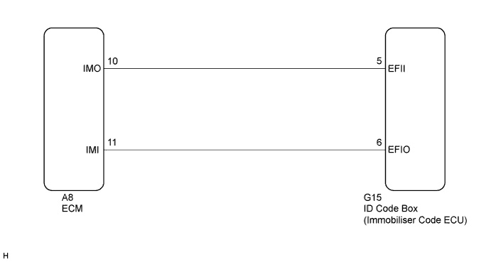
WIRING DIAGRAM
INSPECTION PROCEDURE
Note
-
If the ID code box (immobiliser code ECU) is replaced, register the ECU code and ECU communication ID.
-
If the ECM is replaced, register the ECU communication ID.
PROCEDURE
-
CHECK DTC OUTPUT
-
Clear the DTCs Click here.
-
Recheck for DTCs Click here.
OK B2799 output does not recur.
NG 
RE-REGISTER ECU COMMUNICATION ID Click here
OK 
USE SIMULATION METHOD TO CHECK Click here
-
-
RE-REGISTER ECU COMMUNICATION ID
-
Re-register the ECU communication ID.
NEXT 
-
-
CHECK DTC OUTPUT
-
Clear the DTCs Click here.
-
Recheck for DTCs Click here.
OK B2799 output does not recur.
NG
CHECK CONNECTOR CONNECTION CONDITION Click here
OK
END (ECU COMMUNICATION ID IS DEFECTIVE)
-
-
CHECK CONNECTOR CONNECTION CONDITION
-
Turn the engine switch off.
-
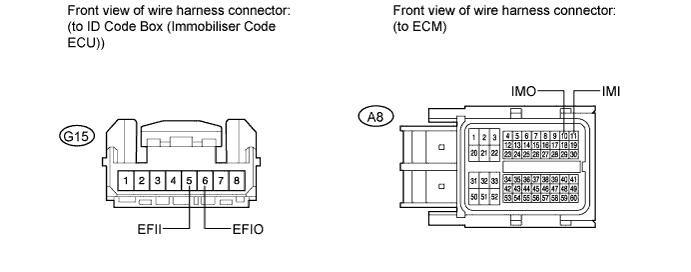
Check that the connectors are properly connected to the ECM and the ID code box (immobiliser code ECU).
OK Connectors are properly connected.
NG 
CONNECT CONNECTORS PROPERLY
OK
-
-
CHECK HARNESS AND CONNECTOR (ID CODE BOX - ECM)
-
Disconnect the ID code box (immobiliser code ECU) connector.
-
Disconnect the ECM connector.
-
Measure the resistance according to the value(s) in the table below.
Standard Resistance Tester Connection Condition Specified Condition G15-5 (EFII) - A8-10 (IMO) Always Below 1 Ω G15-6 (EFIO) - A8-11 (IMI) Always Below 1 Ω G15-5 (EFII) - Body ground Always 10 kΩ or higher G15-6 (EFIO) - Body ground Always 10 kΩ or higher
NG
REPAIR OR REPLACE HARNESS OR CONNECTOR
OK
-
-
REPLACE ECM
-
Replace the ECM Click here for 2GR-FE, Click here for 2AZ-FE).
NEXT
-
-
REGISTER ECU COMMUNICATION ID
-
Register the ECU communication ID.
NEXT
-
-
CHECK DTC OUTPUT
-
Clear the DTCs Click here.
-
Recheck for DTCs Click here.
OK B2799 output does not recur.
NG
REPLACE ID CODE BOX (IMMOBILISER CODE ECU)
OK
END (ECM IS DEFECTIVE)
-