ENGINE IMMOBILISER SYSTEM TERMINALS OF ECU

-
CHECK ENGINE SWITCH
-
Disconnect the G21 engine switch connector.

-
Measure the resistance according to the value(s) in the table below.
Tech Tips
Measure the values on the wire harness side with the connector disconnected.
Tester Connection Wiring Color Terminal Description Condition Specified Condition G21-8 (AGND) - Body ground G - Body ground Ground Always Below 1 Ω If the result is not as specified, there may be a malfunction in the wire harness.
-
Reconnect the G21 engine switch connector.
-
Measure the voltage according to the value(s) in the table below.
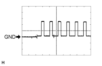
Tester Connection Wiring Color Terminal Description Condition Specified Condition G21-9 (TXCT) - G21-8 (AGND) LG - G Key code output signal After pressing the key (lock switch) Below 1 V G21-9 (TXCT) - G21-8 (AGND) LG - G Key code output signal Key held close to engine switch* Pulse generation
(See waveform 1)
G21-10 (CODE) - G21-8 (AGND) GR - G Demodulated signal of key code data Key not in cabin Below 1 V G21-10 (CODE) - G21-8 (AGND) GR - G Demodulated signal of key code data Key held close to engine switch* Pulse generation
(See waveform 2)
G21-14 (VC5) - G21-8 (AGND) L - G Power supply After pressing the key (lock switch) Below 1 V G21-14 (VC5) - G21-8 (AGND) L - G Power supply Brake pedal depressed* 4.6 to 5.4 V Tech Tips
*: Remove the key battery before performing this inspection.
If the result is not as specified, the engine switch may have a malfunction.
-
Inspect using an oscilloscope.
-
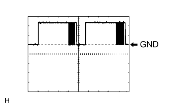
Waveform 1 (Reference)
Item Content Tester Connection G21-9 (TXCT) - G21-8 (AGND) Tool Setting 2 V/DIV., 50 ms./DIV. Condition Key is held close to engine switch* Tech Tips
*: Remove the key battery before performing this inspection.
-
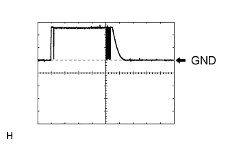
Waveform 2 (Reference)
Item Content Tester Connection G21-10 (CODE) - G21-8 (AGND) Tool Setting 2 V/DIV., 50 ms./DIV. Condition Key is held close to engine switch* Tech Tips
*: Remove the key battery before performing this inspection.
-
-
-
CHECK CERTIFICATION ECU (SMART KEY ECU ASSEMBLY)
-
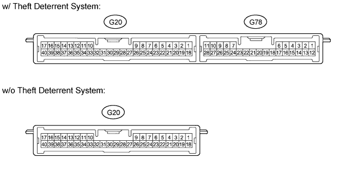
Disconnect the G20 certification ECU (smart key ECU assembly) connector.
-
Measure the resistance and voltage according to the value(s) in the table below.
Tech Tips
Measure the values on the wire harness side with the connector disconnected.
Tester Connection Wiring Color Terminal Description Condition Specified Condition G20-1 (+B) - G20-17 (E) R - W-B +B power supply Always 11 to 14 V G20-17 (E) - Body ground W-B - Body ground Ground Always Below 1 Ω If the result is not as specified, there may be a malfunction in the wire harness.
-
Reconnect the G20 certification ECU (smart key ECU assembly) connector.
-
Measure the resistance and voltage according to the value(s) in the table below.
Tester Connection Wiring Color Terminal Description Condition Specified Condition G20-2 (IND) - Body ground V - Body ground Security indicator light signal Engine switch on (IG), security indicator light off Below 1 V G20-2 (IND) - Body ground V - Body ground Security indicator light signal Immobiliser set state, security indicator light blinks Repeats 11 to 14 V and below 1 V G20-8 (TXCT) - G20-40 (AGND) LG - G Engine switch TXCT output After pressing the key (lock switch) Below 1 V G20-8 (TXCT) - G20-40 (AGND) LG - G Engine switch TXCT output Key held close to engine switch* Pulse generation (See waveform 1) G20-9 (CODE) - G20-40 (AGND) GR - G Engine switch CODE input Key not in cabin Below 1 V G20-9 (CODE) - G20-40 (AGND) GR - G Engine switch CODE input Key held close to engine switch* Pulse generation (See waveform 2) G20-18 (IG) - G20-17 (E) R - W-B Ignition power supply Engine switch off Below 1 V G20-18 (IG) - G20-17 (E) R - W-B Ignition power supply Engine switch on (IG) 11 to 14 V G20-19 (ACC) - G20-17 (E) GR - W-B ACC power supply Engine switch off Below 1 V G20-19 (ACC) - G20-17 (E) GR - W-B ACC power supply Engine switch on (ACC) 11 to 14 V G20-30 (VC5) - G20-40 (AGND) L - G Engine switch power supply After pressing the key (lock switch) Below 1 V G20-30 (VC5) - G20-40 (AGND) L - G Engine switch power supply Brake pedal depressed* 4.6 to 5.4 V G20-40 (AGND) - Body ground G - Body ground Engine switch ground Always Below 1 Ω Tech Tips
*: Remove the key battery before performing this inspection.
If the result is not as specified, the certification ECU (smart key ECU assembly) may have a malfunction.
-
Inspect using an oscilloscope.
-
Waveform 1 (Reference)
Item Content Tester Connection G20-8 (TXCT) - G20-40 (AGND) Tool Setting 2 V/DIV., 50 ms./DIV. Condition Key is held close to engine switch* Tech Tips
*: Remove the key battery before performing this inspection.
-
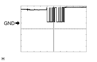
Waveform 2 (Reference)
Item Content Tester Connection G20-9 (CODE) - G20-40 (AGND) Tool Setting 2 V/DIV., 50 ms./DIV. Condition Key is held close to engine switch* Tech Tips
*: Remove the key battery before performing this inspection.
-
-
-
CHECK ID CODE BOX (IMMOBILISER CODE ECU)
-
Disconnect the G15 ID code box (immobiliser code ECU) connector.

-
Measure the resistance and voltage according to the value(s) in the table below.
Tech Tips
Measure the values on the wire harness side with the connector disconnected.
Tester Connection Wiring Color Terminal Description Condition Specified Condition G15-1 (+B) - G15-8 (GND) R - W-B +B power supply Always 11 to 14 V G15-8 (GND) - Body ground W-B - Body ground Ground Always Below 1 Ω If the result is not as specified, there may be a malfunction in the wire harness.
-
Reconnect the G15 ID code box (immobiliser code ECU) connector.
-
Measure the voltage according to the value(s) in the table below.
Tester Connection Wiring Color Terminal Description Condition Specified Condition G15-5 (EFII) - G15-8 (GND) G - W-B ECM output signal Engine switch off 11 to 14 V G15-5 (EFII) - G15-8 (GND) G - W-B ECM output signal Within 3 seconds after the starter operates and initial combustion occurs, or within 3 seconds after engine switch first turned on (IG) after battery disconnected and connected Pulse generation
(See waveform 1)
G15-6 (EFIO) - G15-8 (GND) R - W-B ECM input signal Engine switch off Below 1 V G15-6 (EFIO) - G15-8 (GND) R - W-B ECM input signal Engine switch on (IG) Pulse generation
(See waveform 2)
If the result is not as specified, the ID code box (immobiliser code ECU) may have a malfunction.
-
Inspect using an oscilloscope.
-
Waveform 1 (Reference)
Item Content Tester Connection G15-5 (EFII) - G15-8 (GND) Tool Setting 5 V/DIV., 500 ms./DIV. Condition Within 3 seconds after the starter operates and initial combustion occurs, or within 3 seconds after engine switch first turned on (IG) after battery disconnected and connected -
Waveform 2 (Reference)
Item Content Tester Connection G15-6 (EFIO) - G15-8 (GND) Tool Setting 5 V/DIV., 50 ms./DIV. Condition Engine switch on (IG)
-
-
-
CHECK STEERING LOCK ECU (STEERING LOCK ACTUATOR ASSEMBLY)
-
Disconnect the G22 steering lock ECU (steering lock actuator assembly) connector.

-
Measure the resistance and voltage according to the value(s) in the table below.
Tech Tips
Measure the values on the wire harness side with the connector disconnected.
Tester Connection Wiring Color Terminal Description Condition Specified Condition G22-1 (GND) - Body ground W-B - Body ground Ground Always Below 1 Ω G22-2 (SGND) - Body ground W-B - Body ground Ground Always Below 1 Ω G22-6 (IG2) - Body ground B - Body ground Ignition power supply Engine switch off Below 1 V G22-6 (IG2) - Body ground B - Body ground Ignition power supply Engine switch on (IG) 11 to 14 V G22-7 (B) - Body ground B - Body ground +B power supply Always 11 to 14 V If the result is not as specified, there may be a malfunction in the wire harness.
-
-
CHECK ECM
-
The values listed under "Specified Condition" are reference values. Because waterproof connectors are used for ECM, inspections can not be performed with the connectors connected.
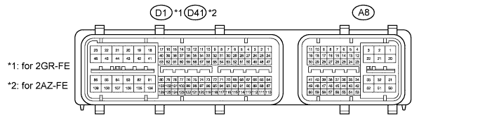
Tester Connection Wiring Color Terminal Description Condition Specified Condition D1-81 (E1) - Body ground*1
D41-104 (E1) - Body ground*2
BR - Body ground Ground Always Below 1 Ω A8-10 (IMO) - D1-81 (E1)*1
A8-10 (IMO) - D41-104 (E1)*2
BR - BR ID code box (immobiliser code ECU) input signal Engine switch off 11 to 14 V A8-10 (IMO) - D1-81 (E1)*1
A8-10 (IMO) - D41-104 (E1)*2
BR - BR ID code box (immobiliser code ECU) input signal Within 3 seconds after the starter operates and initial combustion occurs, or within 3 seconds after engine switch first turned on (IG) after battery disconnected and connected Pulse generation
(See waveform 1)
A8-11 (IMI) - D1-81 (E1)*1
A8-11 (IMI) - D41-104 (E1)*2
G - BR ID code box (immobiliser code ECU) ouotput signal Engine switch off Below 1 V A8-11 (IMI) - D1-81 (E1)*1
A8-11 (IMI) - D41-104 (E1)*2
G - BR ID code box (immobiliser code ECU) output signal Engine switch on (IG) Pulse generation
(See waveform 2)
-
*1: for 2GR-FE
-
*2: for 2AZ-FE
-
-
Waveform:
-
Waveform 1 (Reference)
Item Content Tester Connection for 2GR-FE A8-10 (IMO) - D1-81 (E1) for 2AZ-FE A8-10 (IMO) - D41-104 (E1) Tool Setting 5 V/DIV., 500 ms./DIV. Condition Within 3 seconds after the starter operates and initial combustion occurs, or within 3 seconds after engine switch first turned on (IG) after battery disconnected and connected -
Waveform 2 (Reference)
Item Content Tester Connection for 2GR-FE A8-11 (IMI) - D1-81 (E1) for 2AZ-FE A8-11 (IMI) - D41-104 (E1) Tool Setting 5 V/DIV., 50 ms./DIV. Condition Engine switch on (IG)
-
-
-
CHECK MAIN BODY ECU
-
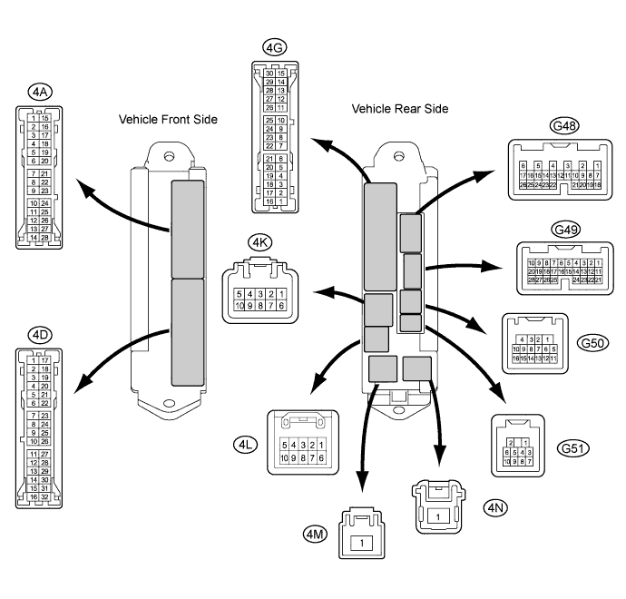
Disconnect the 4A and 4K main body ECU connectors.
-
Measure the resistance and voltage according to the value(s) in the table below.
Tech Tips
Measure the values on the wire harness side with the connectors disconnected.
Tester Connection Wiring Color Terminal Description Condition Specified Condition 4A-3 (GND2) - Body ground W-B - Body ground Ground Always Below 1 Ω 4K-1 (BECU) - Body ground R - Body ground Battery power supply Always 11 to 14 V 4K-9 (BATB) - Body ground W - Body ground Ignition power supply Always 11 to 14 V If the result is not as specified, there may be a malfunction in the wire harness.
-
-
CHECK COMBINATION METER ASSEMBLY
-
Disconnect the G19 combination meter assembly connector.

-
Measure the voltage and resistance according to the value(s) in the table below.
Tech Tips
Measure the values on the wire harness side with the connector disconnected.
Terminal No. (Symbol) Wiring Color Terminal Description Condition Specified Condition G19-1 (IG2) - Body ground G - Body ground Engine switch signal Engine switch on (IG) 11 to 14 V G19-1 (IG2) - Body ground G - Body ground Engine switch signal Engine switch off Below 1 V G19-2 (B) - Body ground SB - Body ground Battery Always 11 to 14 V G19-3 (EP) - Body ground BR - Body ground Ground (Signal ground) Always Below 1 Ω G19-6 (LP) - Body ground V - Body ground Security indicator light signal Engine switch on (IG), security indicator light off Below 1 V G19-6 (LP) - Body ground V - Body ground Security indicator light signal Immobiliser set state, security indicator light blinks Repeats 11 to 14 V and below 1 V If the result is not as specified, there may be a malfunction in the wire harness.
-