SMART ENTRY AND START SYSTEM (for Entry Function) OPERATION CHECK

-
SMART ENTRY AND START SYSTEM OPERATION INSPECTION
-
Check the entry unlock function.
-
Use the wireless lock operation to lock the doors. With the key outside the vehicle, touch a door outside handle (touch sensor) and check that the door unlocks.
-
-
Check the entry unlock operation detection area.
-
Step 1: Hold the key at the same height as the door outside handle (approximately 0.8 m (2.62 ft.)). Make sure that the direction of the key is as shown in the illustration.
-
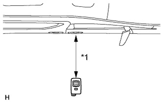
Text in Illustration *1 0.7 to 1.0 m Step 2: Check that when the key is brought within 0.7 to 1.0 m (2.30 to 3.28 ft.) of the vehicle, the system enters unlock standby mode.
Tech Tips
When the system enters unlock standby mode, the key LED illuminates.
-
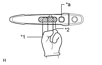
Text in Illustration *1 Glove *2 Detection Area (Inner Side) *a Lock Switch Step 3: After the system enters unlock standby mode, touch the outside handle sensor within 3 seconds. Check that the door unlocks.
Note
The key may not be able to communicate with the system within a 0.2 m (0.656 ft.) radius of each outside handle.
-
Step 4: Repeat step 2 and step 3 for the remaining doors.
-
Step 5: Inspect the door electrical key oscillator response sensitivity. Wear protective gloves, set the system to unlock standby mode, and check that touching the backside of the door outside handle (the highlighted area shown in the illustration) with your finger causes the door to unlock.
Note
When touching the highlighted area, touching too quickly or having extended contact may not trigger the sensor. In such a case, the door will not unlock.
-
Step 6: Repeat step 5 for the remaining doors.
-
-
Check the entry lock function.
-
Text in Illustration *1 Approximately 0.3 m Step 1: Close all doors of the vehicle. With the key outside the vehicle, check that pressing the lock switch locks the doors.
Tech Tips
-
When pressing the lock switch, hold the electrical key transmitter about 1 m (3.28 ft.) above the ground and about 0.3 m (0.984 ft.) away from the vehicle as shown in the illustration.
-
Due to the key being unable to communicate with the system within a 0.2 m (0.656 ft.) distance from the outside handle, do not press the lock switch with the same hand that is holding the key. The doors may not lock.
-
If the key lock-in prevention function buzzer* sounds, radio waves from the indoor electrical key oscillator may be leaking from the vehicle. Perform the same check for the front passenger side and rear doors.
-
*: w/ Wireless Buzzer Function
-
-
Step 2: Repeat step 1 for the remaining doors.
-
-
Check the entry back door open function.
-
Close the back door. With the key outside the vehicle, check that pressing the back door opener switch assembly opens the back door.
-
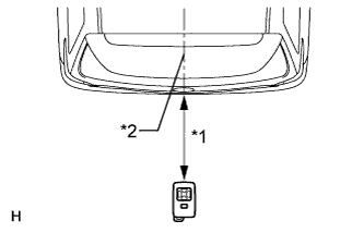
Text in Illustration *1 0.7 to 1.0 m *2 Vehicle Center Inspect the entry back door open operation's detection area. Hold the key at the same height as the back door opener switch assembly (approximately 0.8 m (2.62 ft.)) aligning it with the center of the rear of the vehicle. Make sure that the direction of the key is as shown in the illustration. Check that when the key is brought within 0.7 to 1.0 m (2.30 to 3.28 ft.) of the vehicle, pressing the back door opener switch assembly opens the back door.
-
-
Check the engine start function.
-
When the engine is stopped:
With the key inside the vehicle and the brake pedal depressed, check that pressing the engine switch releases the steering wheel lock and starts the engine.
Tech Tips
The engine can be started only when the engine switch indicator illuminates in green.
-
When the engine is running:
With the key inside the vehicle, check that pressing the engine switch stops the engine and activates the steering wheel lock.
Tech Tips
The shift lever must be in P to stop the engine.
-
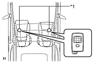
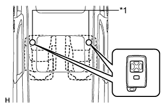
Text in Illustration *1 Inspection Point Inspect the detection area for the engine start function (for front floor). Make sure that the direction of the electrical key is as shown in the illustration. When the electrical key is in either of the 2 inspection points shown in the illustration, check that the engine can start.
Note
The engine cannot be started when the key is on the instrument panel, rear package tray or in the glove box.
-
Text in Illustration *1 Inspection Point Inspect the detection area for the engine start function (for center floor). Make sure that the direction of the electrical key is as shown in the illustration. When the electrical key is in either of the 2 inspection points shown in the illustration, check that the engine can start.
Note
The engine cannot be started when the key is on the instrument panel, rear package tray or in the glove box.
-
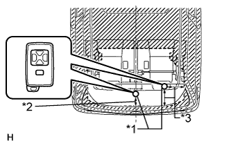
Text in Illustration *1 Inspection Point *2 0.1 m (0.328 ft.) *3 0.2 m (0.656 ft.) Inspect the detection area for the engine start function (for rear floor). Make sure that the direction of the electrical key is as shown in the illustration. When the electrical key is in either of the 2 inspection points shown in the illustration, check that the engine can start.
Note
The engine cannot be started when the key is on the instrument panel, rear package tray or in the glove box.
-
-
Check the key cancel function.
-
While the engine switch is on (IG), check that the back door opener switch assembly (opener switch) is the only switch that can be operated in the smart entry and start system.
-
While the key cancel function (smart entry and start system cancel function) is on, check that all functions of the smart entry and start system cannot be operated.
-
-
Check the answer-back function (hazard warning light flashing and buzzer* sounding).
Entry Operation Hazard Warning Light Buzzer* Entry Door Lock Flashes once Sounds once Entry Door Unlock Flashes twice Sounds twice Entry Back Door Open Flashes twice Sounds twice
-
*: w/ Wireless Buzzer Function
-
-
Check that the key reminder warning buzzer sounds.
-
With the key inside the vehicle, close the driver side door. Then turn the engine switch off or on (ACC).
-
Open the driver side door and check that the buzzer sounds intermittently.
-
-
Check that the key reminder warning buzzer stops.
-
When the buzzer is sounding, check that the buzzer stops sounding if either of the following is performed:
-
Close the driver side door (front door courtesy light switch is off).
-
Turn the engine switch on (IG).
-
-
-
-
KEY DIAGNOSTIC MODE
Tech Tips
Key diagnostic mode checks if the key within a selected oscillator detection area is operating normally. The results are output through the wireless door lock buzzer.
-
Connect the intelligent tester to the DLC3.
-
Turn the engine switch on (IG).
-
Turn the intelligent tester on.
-
Enter the following menus: Body / Entry & Start / Key Communication Check.
-
Check the values by referring to the table below.
Entry & Start (Certification ECU (Smart Key ECU Assembly)) Tester Display Inspection Range Overhead + Driver Side*1 Door electrical key oscillator (for driver side) Overhead + Passenger Side*2 Door electrical key oscillator (for front passenger side) Overhead + Front Room*3 Indoor electrical key oscillator (for front floor) Overhead + Rear Room*4 Indoor electrical key oscillator (for center floor) Overhead + Back Door (inside)*5 Indoor electrical key oscillator (for rear floor) Overhead + Back Door*6 Outside electrical key oscillator (for rear side) -
When the key is brought near the selected oscillator, check that the wireless door lock buzzer sounds.
-
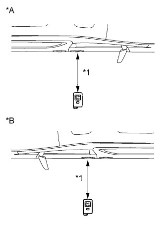
Text in Illustration *A for RHD *B for LHD *1 0.7 to 1.0 m *1: Door electrical key oscillator (for driver side)
Tech Tips
-
Hold the key at the same height as the door outside handle (0.7 to 1.0 m (2.30 to 3.28 ft.)). Make sure that the direction of the key is as shown in the illustration.
-
*2: Perform the same inspection above for the door electrical key oscillator (for front passenger side).
-
-
Text in Illustration *1 Inspection Point *3: Indoor electrical key oscillator (for front floor)
Tech Tips
Place the key on the driver or front passenger seat cushion.
-
Text in Illustration *1 Inspection Point *4: Indoor electrical key oscillator (for center floor)
Tech Tips
Place the key on the rear No. 1 seat cushion.
-
Text in Illustration *1 Inspection Point *2 0.1 m (0.328 ft.) *3 0.2 m (0.656 ft.) *5: Indoor electrical key oscillator (for rear floor)
Tech Tips
Place the key on the luggage area.
-
Text in Illustration *1 0.7 to 1.0 m (2.30 to 3.28 ft.) *2 Vehicle Center *6: Outside electrical key oscillator (for rear side)
Tech Tips
Hold the key at the same height as the rear bumper upper surface and align with the center of the rear of the vehicle, as shown in the illustration.
-
-