SMART ENTRY AND START SYSTEM (for Start Function), Diagnostic DTC:B2289

| DTC Code | DTC Name |
|---|---|
| B2289 | Key Collation Waiting Time Over |
DESCRIPTION
This DTC is stored when there is a problem with the LIN communication between the main body ECU and the certification ECU (smart key ECU assembly), or when there is a problem with in-vehicle key collation (key certification).
| DTC No. | DTC Detection Condition | Trouble Area |
|---|---|---|
| B2289 | Either condition is met:
|
|
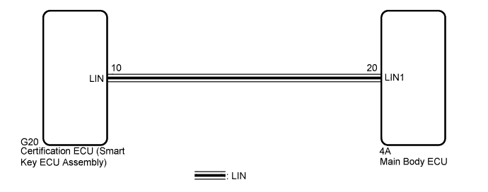
WIRING DIAGRAM
INSPECTION PROCEDURE
PROCEDURE
-
CHECK FOR DTC
-
Connect the intelligent tester to the DLC3.
-
Turn the engine switch on (IG).
-
Turn the intelligent tester on.
-
Check for DTCs.
Result Inspection Result Proceed to DTC B2289 only is output A DTC B2287 is also output B DTCs are not output C
B 
GO TO LIN COMMUNICATION SYSTEM (B2287) Click here
C
USE SIMULATION METHOD TO CHECK Click here
A 
-
-
CHECK FOR DTC
-
Clear the DTCs Click here.
-
Check if engine immobiliser DTCs or LIN communication DTCs are output.
Result Result Proceed to DTCs are not output A Engine immobiliser DTC is output B LIN communication DTC is output C
B
GO TO ENGINE IMMOBILISER SYSTEM (DIAGNOSTIC TROUBLE CODE CHART) Click here
C
GO TO LIN COMMUNICATION SYSTEM (DIAGNOSTIC TROUBLE CODE CHART) Click here
A
-
-
CHECK SMART ENTRY AND START SYSTEM (ENTRY FUNCTION)
-
Remove the battery of the electrical key transmitter Click here.
-
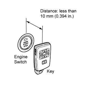
Hold the key close to the engine switch.
-
Check that the engine switch can be turned on (IG).
OK Power source mode is turned on.
NG
GO TO SMART ENTRY AND START SYSTEM (Room Oscillator does not Recognize Key) Click here
OK
-
-
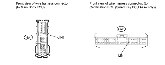
CHECK HARNESS AND CONNECTOR (MAIN BODY ECU - CERTIFICATION ECU (SMART KEY ECU ASSEMBLY))
-
Disconnect the 4A connector from the main body ECU.
-
Disconnect the G20 connector from the certification ECU (smart key ECU assembly).
-
Measure the resistance according to the value(s) in the table below.
Standard Resistance Tester Connection Condition Specified Condition 4A-20 (LIN1) - G20-10 (LIN) Always Below 1 Ω 4A-20 (LIN1) or G20-10 (LIN) - Body ground Always 10 kΩ or higher
NG
REPAIR OR REPLACE HARNESS OR CONNECTOR (MAIN BODY ECU - CERTIFICATION ECU (SMART KEY ECU ASSEMBLY))
OK
-
-
REPLACE MAIN BODY ECU
-
Replace the main body ECU Click here.
NEXT
-
-
CHECK FOR DTC
-
Clear the DTCs Click here.
-
Check if DTC B2289 is output.
OK DTC B2289 is not output.
NG
REPLACE CERTIFICATION ECU (SMART KEY ECU ASSEMBLY)
OK 
END (MAIN BODY ECU WAS DEFECTIVE)
-