SLIDE DOOR LOCK INSPECTION

-
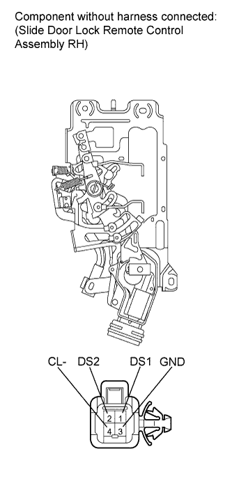
INSPECT SLIDE DOOR LOCK REMOTE CONTROL ASSEMBLY RH
-
Inspect the door handle switch.
-
Measure the resistance according to the values in the table below. (w/o Power Slide Door System)
Standard Resistance Tester Connection Condition Specified Condition 2 (DS2) - 3 (GND) Inside door handle not operated Below 1 Ω 2 (DS2) - 3 (GND) Inside door handle turned to open 10 kΩ or higher
-
If the result is not as specified, replace the slide door lock remote control assembly RH.
-
-
Measure the resistance according to the values in the table below. (w/ Power Slide Door System)
Standard Resistance Tester Connection Condition Specified Condition 1 (DS1) - 3 (GND) Inside door handle not operated 10 kΩ or higher 1 (DS1) - 3 (GND) Inside door handle turned to close Below 1 Ω 2 (DS2) - 3 (GND) Inside door handle not operated 10 kΩ or higher 2 (DS2) - 3 (GND) Inside door handle turned to open Below 1 Ω 4 (CL-) - Body ground Always Below 1 Ω
-
If the result is not as specified, replace the slide door lock remote control assembly RH.
-
-
-
-
INSPECT REAR DOOR LOCK ACTUATOR ASSEMBLY RH
-
Inspect the door lock operation.
-
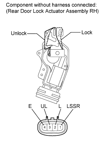
Apply battery voltage to the motor terminals and check the operation of the door lock motor.
OK Measurement Condition Specified Condition Battery positive (+) → 2 (L)
Battery negative (-) → 3 (UL)
Lock Battery positive (+) → 3 (UL)
Battery negative (-) → 2 (L)
Unlock
-
If the result is not as specified, replace the rear door lock actuator assembly RH.
-
-
-
Inspect the unlock detection switch.
-
Measure the resistance according to the values in the table below.
Standard Resistance Tester Connection Condition Specified Condition 1 (LSSR) - 4 (E) Lock 10 kΩ or higher 1 (LSSR) - 4 (E) Unlock Below 1 Ω
-
If the result is not as specified, replace the rear door lock actuator assembly RH.
-
-
-
-
INSPECT SLIDE DOOR LOCK REMOTE CONTROL ASSEMBLY LH
-

Inspect the door handle switch.
-
Measure the resistance according to the values in the table below.
Standard Resistance Tester Connection Condition Specified Condition 1 (DS1) - 3 (GND) Inside door handle not operated 10 kΩ or higher 1 (DS1) - 3 (GND) Inside door handle turned to close Below 1 Ω 2 (DS2) - 3 (GND) Inside door handle not operated 10 kΩ or higher 2 (DS2) - 3 (GND) Inside door handle turned to open Below 1 Ω
-
If the result is not as specified, replace the slide door lock remote control assembly LH.
-
-
-
-
INSPECT REAR DOOR LOCK ACTUATOR ASSEMBLY LH
-
Inspect the door lock operation.
-
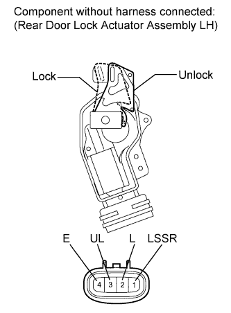
Apply battery voltage to the motor terminals and check the operation of the door lock motor.
OK Measurement Condition Specified Condition Battery positive (+) → 2 (L)
Battery negative (-) → 3 (UL)
Lock Battery positive (+) → 3 (UL)
Battery negative (-) → 2 (L)
Unlock
-
If the result is not as specified, replace the rear door lock actuator assembly LH.
-
-
-
Inspect the unlock detection switch.
-
Measure the resistance according to the values in the table below.
Standard Resistance Tester Connection Condition Specified Condition 1 (LSSR) - 4 (E) Lock 10 kΩ or higher 1 (LSSR) - 4 (E) Unlock Below 1 Ω
-
If the result is not as specified, replace the rear door lock actuator assembly LH.
-
-
-
-
INSPECT REAR SLIDE DOOR LOCK ASSEMBLY LH
-
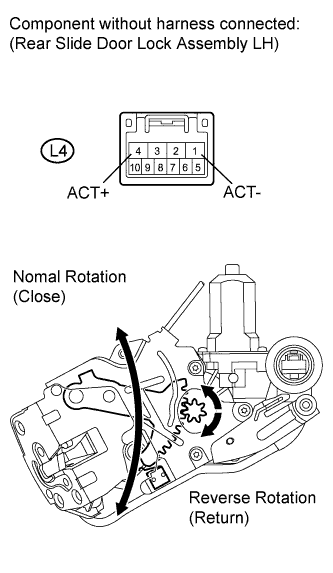
Check the operation of the slide door closer motor.
OK Tester Connection Condition Specified Condition L4-4 (ACT+) - L4-1 (ACT-) Battery voltage is applied to terminal L4-4 (ACT+) Close operation L4-4 (ACT+) - L4-1 (ACT-) Battery voltage is applied to terminal L4-1 (ACT-) Return operation -
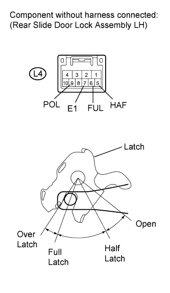
Measure the resistance according to the values in the table below.
Standard Resistance Full Latch Switch Tester Connection Condition Specified Condition L4-6 (FUL) - L4-7 (E1) Open Below 1 Ω L4-6 (FUL) - L4-7 (E1) Half latch Below 1 Ω L4-6 (FUL) - L4-7 (E1) Full latch 10 kΩ or higher L4-6 (FUL) - L4-7 (E1) Over latch 10 kΩ or higher Half Latch Switch Tester Connection Condition Specified Condition L4-5 (HAF) - L4-7 (E1) Open Below 1 Ω L4-5 (HAF) - L4-7 (E1) Half latch 10 kΩ or higher L4-5 (HAF) - L4-7 (E1) Full latch 10 kΩ or higher L4-5 (HAF) - L4-7 (E1) Over latch 10 kΩ or higher Pawl Switch Tester Connection Condition Specified Condition L4-9 (POL) - L4-7 (E1) Open 10 kΩ or higher L4-9 (POL) - L4-7 (E1) Between open and half latch 10 kΩ or higher → Below 1 Ω L4-9 (POL) - L4-7 (E1) Half latch 10 kΩ or higher L4-9 (POL) - L4-7 (E1) Between half latch and full latch 10 kΩ or higher → Below 1 Ω L4-9 (POL) - L4-7 (E1) Full latch 10 kΩ or higher L4-9 (POL) - L4-7 (E1) Over latch 10 kΩ or higher -
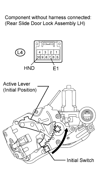
Measure the resistance according to the values in the table below.
Standard Resistance Tester Connection Condition Specified Condition L4-10 (HND) - L4-7 (E1) Initial position 10 kΩ or higher L4-10 (HND) - L4-7 (E1) Except initial position Below 1 Ω
-
-
INSPECT REAR SLIDE DOOR LOCK ASSEMBLY RH
-
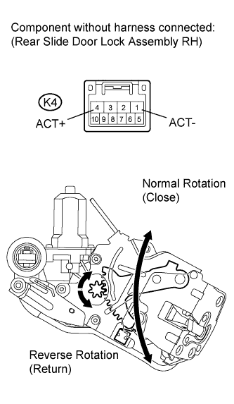
Check the operation of the slide door closer motor.
OK Tester Connection Connection Specified Condition K4-4 (ACT+) - K4-1 (ACT-) Battery voltage is applied to terminal 4 (ACT+) Close operation K4-4 (ACT+) - K4-1 (ACT-) Battery voltage is applied to terminal 1 (ACT-) Return operation -
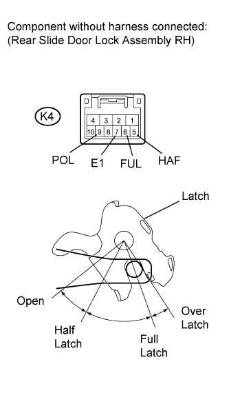
Measure the resistance according to the values in the table below.
Standard Resistance Full Latch Switch Tester Connection Condition Specified Condition K4-6 (FUL) - K4-7 (E1) Open Below 1 Ω K4-6 (FUL) - K4-7 (E1) Half latch Below 1 Ω K4-6 (FUL) - K4-7 (E1) Full latch 10 kΩ or higher K4-6 (FUL) - K4-7 (E1) Over latch 10 kΩ or higher Half Latch Switch Tester Connection Condition Specified Condition K4-5 (HAF) - K4-7 (E1) Open Below 1 Ω K4-5 (HAF) - K4-7 (E1) Half latch 10 kΩ or higher K4-5 (HAF) - K4-7 (E1) Full latch 10 kΩ or higher K4-5 (HAF) - K4-7 (E1) Over latch 10 kΩ or higher Pawl Switch Tester Connection Condition Specified Condition K4-9 (POL) - K4-7 (E1) Open 10 kΩ or higher K4-9 (POL) - K4-7 (E1) Between open and half latch 10 kΩ or higher → Below 1 Ω K4-9 (POL) - K4-7 (E1) Half latch 10 kΩ or higher K4-9 (POL) - K4-7 (E1) Between half latch and full latch 10 kΩ or higher → Below 1 Ω K4-9 (POL) - K4-7 (E1) Full latch 10 kΩ or higher K4-9 (POL) - K4-7 (E1) Over latch 10 kΩ or higher -
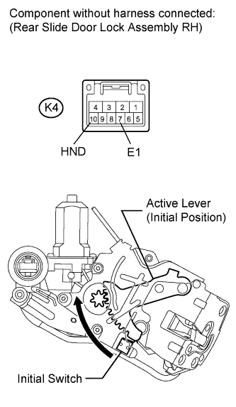
Measure the resistance according to the values in the table below.
Standard Resistance Tester Connection Condition Specified Condition K4-10 (HND) - K4-7 (E1) Initial position 10 kΩ or higher K4-10 (HND) - K4-7 (E1) Except initial position Below 1 Ω
-