FRONT DOOR LOCK INSPECTION

-
INSPECT FRONT DOOR LOCK ASSEMBLY (for Driver Side)
-

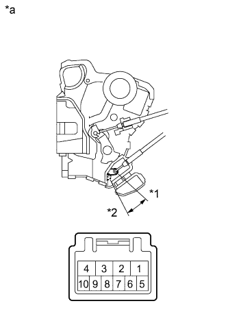
Text in Illustration *a Component without harness connected
Front Door Lock Assembly RH
*1 Unlock *2 Lock for RHD:
Apply battery voltage to the motor terminals and check the operation of the door lock motor.
OK Measurement Condition Result Battery positive (+) → 4 (L)
Battery negative (-) → 1 (UL)
Locks Battery positive (+) → 1 (UL)
Battery negative (-) → 4 (L)
Unlocks -
Measure the resistance according to the values in the table below.
Standard Resistance Door Lock Position Switch Tester Connection Measurement Condition Door Lock Condition Specified Condition 7 - 8 Battery positive (+) → Terminal 4
Battery negative (-) → Terminal 1
Locked 10 kΩ or higher 7 - 8 Battery positive (+) → Terminal 1
Battery negative (-) → Terminal 4
Unlocked Below 1 Ω -
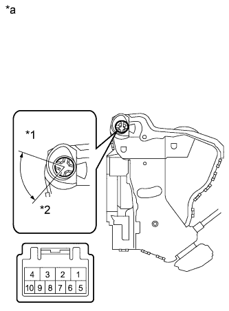
Text in Illustration *a Component without harness connected
Front Door Lock Assembly LH
*1 Unlock *2 Lock for LHD:
Apply battery voltage to the motor terminals and check the operation of the door lock motor.
OK Measurement Condition Result Battery positive (+) → 4 (L)
Battery negative (-) → 1 (UL)
Locks Battery positive (+) → 1 (UL)
Battery negative (-) → 4 (L)
Unlocks -
Measure the resistance according to the values in the table below.
Standard Resistance Door Lock Position Switch Tester Connection Measurement Condition Door Lock Condition Specified Condition 7 - 8 Battery positive (+) → Terminal 4
Battery negative (-) → Terminal 1
Locked 10 kΩ or higher 7 - 8 Battery positive (+) → Terminal 1
Battery negative (-) → Terminal 4
Unlocked Below 1 Ω -
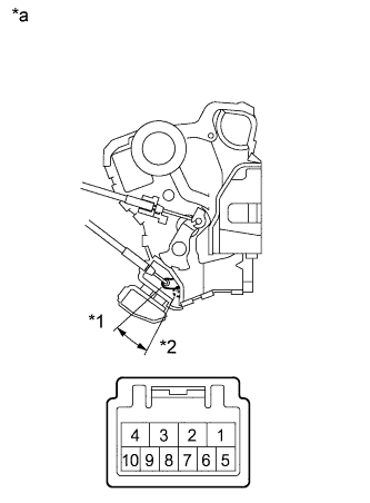
Text in Illustration *a Component without harness connected
Front Door Lock Assembly RH
*1 Lock *2 Unlock for RHD:
Measure the resistance according to the values in the table below.
Standard Resistance Door Key Lock Switch Tester Connection Condition Specified Condition 8 - 6 Locked Below 1 Ω 8 - 6
8 - 5
OFF (Free) 10 kΩ or higher 8 - 5 Unlocked Below 1 Ω If the result is not as specified, replace the door lock assembly.
-
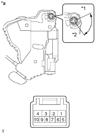
Text in Illustration *a Component without harness connected
Front Door Lock Assembly LH
*1 Lock *2 Unlock for LHD:
Measure the resistance according to the values in the table below.
Standard Resistance Door Key Lock Switch Tester Connection Condition Specified Condition 7 - 9 Locked Below 1 Ω 7 - 9
7 - 10
OFF (Free) 10 kΩ or higher 7 - 10 Unlocked Below 1 Ω If the result is not as specified, replace the door lock assembly.
-
-
INSPECT FRONT DOOR LOCK ASSEMBLY (for Passenger Side)
-

Text in Illustration *a Component without harness connected
Front Door Lock Assembly LH
*1 Unlock *2 Lock for RHD:
Apply battery voltage to the motor terminals and check the operation of the door lock motor.
OK Measurement Condition Result Battery positive (+) → Terminal 4
Battery negative (-) → Terminal 1
Locks Battery positive (+) → Terminal 1
Battery negative (-) → Terminal 4
Unlocks If the result is not as specified, replace the door lock assembly.
-
Measure the resistance according to the values in the table below.
Standard Resistance Door Lock Position Switch Tester Connection Measurement Condition Door Lock Condition Specified Condition 7 - 8 Battery positive (+) → Terminal 4
Battery negative (-) → Terminal 1
Locked 10 kΩ or higher 7 - 8 Battery positive (+) → Terminal 1
Battery negative (-) → Terminal 4
Unlocked Below 1 Ω If the result is not as specified, replace the door lock assembly.
-
Text in Illustration *a Component without harness connected
Front Door Lock Assembly RH
*1 Unlock *2 Lock for LHD:
Apply battery voltage to the motor terminals and check the operation of the door lock motor.
OK Measurement Condition Result Battery positive (+) → Terminal 4
Battery negative (-) → Terminal 1
Locks Battery positive (+) → Terminal 1
Battery negative (-) → Terminal 4
Unlocks If the result is not as specified, replace the door lock assembly.
-
Measure the resistance according to the values in the table below.
Standard Resistance Door Lock Position Switch Tester Connection Measurement Condition Door Lock Condition Specified Condition 7 - 8 Battery positive (+) → Terminal 4
Battery negative (-) → Terminal 1
Locked 10 kΩ or higher 7 - 8 Battery positive (+) → Terminal 1
Battery negative (-) → Terminal 4
Unlocked Below 1 Ω If the result is not as specified, replace the door lock assembly.
-