DESCRIPTION
The main body ECU receives signals from the steering lock actuator assembly (steering lock ECU) via a direct line and via a LIN communication line. If the information received via these 2 lines is inconsistent, this DTC will be stored.
When the main body ECU is replaced with a new one and the negative (-) battery terminal is connected, the power source mode becomes IG-ON mode. When the battery is removed and reinstalled, the power source mode that was selected when the battery was removed is restored.
| DTC No. | DTC Detection Condition | Trouble Area |
|---|---|---|
| B2285 | Information received by the main body ECU from the steering lock actuator assembly (steering lock ECU) via a direct line and a via the LIN communication line is inconsistent. |
|
INSPECTION PROCEDURE
Check the connector connections and terminals to make sure that there are no abnormalities such as loose connections, deformation, etc.
PROCEDURE
- Click here
PERFORM INITIALIZATION (STEERING LOCK SYSTEM)
-
Move the shift lever to P.
-
Turn the engine switch off.
-
Open the driver door.
-
Close the driver door.
- NEXTClick here
-
- Click here
CHECK FOR DTC
-
Connect the intelligent tester to the DLC3.
-
Clear the DTCs (Click here).
-
Check if DTC B2285 is output.
OK DTC B2285 is not output.
- OKClick here
- NGClick here
-
- Click here
READ VALUE USING INTELLIGENT TESTER
-
Turn the engine switch on (IG).
-
Turn the intelligent tester on.
-
Enter the following menus: Body / Main Body / Data List.
-
Read the Data List according to the display on the intelligent tester.
Table 1. Main Body Tester Display Measurement Item/Range Normal Condition Diagnostic Note Steering Unlock Switch Steering lock condition / ON or OFF ON: Steering unlocked (Engine switch on (ACC))
OFF: Steering locked (Engine switch off)
- OK ON (steering is unlocked) and OFF (steering is locked) appear on the screen.
- OKClick here
- NGClick here
-
- Click here
REPLACE MAIN BODY ECU
-
Replace the main body ECU (Click here).
- NEXTClick here
-
- Click here
CHECK FOR DTC
-
Clear the DTCs (Click here).
-
Check if DTC B2285 is output.
OK DTC B2285 is not output.
- OKClick here
- NGClick here
-
- Click here
CHECK HARNESS AND CONNECTOR (MAIN BODY ECU - STEERING LOCK ECU)
-
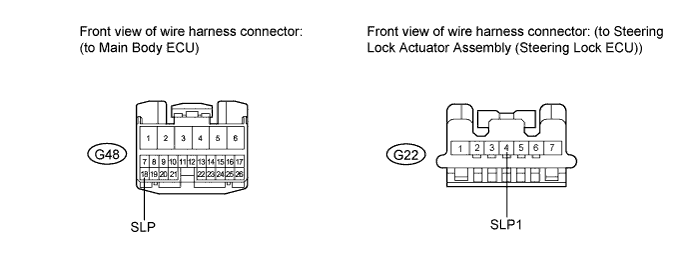
Disconnect the G48 connector from the main body ECU.
-
Disconnect the G22 connector from the steering lock actuator assembly (steering lock ECU).
-
Measure the resistance according to the value(s) in the table below.
Standard Resistance Tester Connection Condition Specified Condition G48-18 (SLP) - G22-4 (SLP1) Always Below 1 Ω G48-18 (SLP) or G22-4 (SLP1) - Body ground Always 10 kΩ or higher
- OKClick here
- NGClick here
-
- Click here
REPLACE MAIN BODY ECU
-
Replace the main body ECU (Click here).
- NEXTClick here
-
- Click here
CHECK FOR DTC
-
Clear the DTCs (Click here).
-
Check if DTC B2285 is output.
OK DTC B2285 is not output.
- OKClick here
- NGClick here
-
- Click here
END (INITIALIZATION WAS NOT COMPLETED)
- Click here
REPLACE STEERING LOCK ACTUATOR ASSEMBLY (STEERING LOCK ECU)Click here
- Click here
END (MAIN BODY ECU WAS DEFECTIVE)
- Click here
REPAIR OR REPLACE HARNESS OR CONNECTOR (MAIN BODY ECU - STEERING LOCK ECU)
- Click here
REPLACE STEERING LOCK ACTUATOR ASSEMBLY (STEERING LOCK ECU)Click here
- Click here
END (MAIN BODY ECU WAS DEFECTIVE)