SMART ENTRY AND START SYSTEM (for Start Function), Diagnostic DTC:B2283

| DTC Code | DTC Name |
|---|---|
| B2283 | Vehicle Speed Sensor Malfunction |
DESCRIPTION
The skid control ECU converts the wheel speed sensor signals into a 4-pulse signal and sends it to the combination meter. After this signal is converted into a more precise rectangular waveform by the waveform shaping circuit inside the combination meter, it is then transmitted to the main body ECU. The main body ECU determines the vehicle speed based on the frequency of this pulse signal.
Tech Tips
When the main body ECU is replaced with a new one and the cable from the negative (-) battery terminal is connected, the power source mode becomes IG-ON mode. When the battery is removed and reinstalled, the power source mode that was selected when the battery was removed is restored.
| DTC No. | DTC Detection Condition | Trouble Area |
|---|---|---|
| B2283 | Both conditions below are met:
|
|
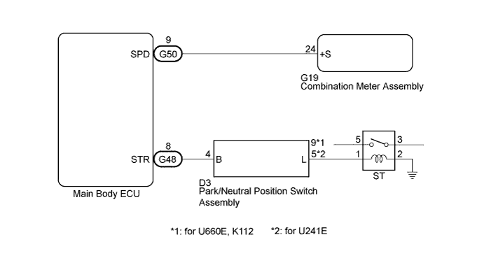
WIRING DIAGRAM
INSPECTION PROCEDURE
PROCEDURE
-
CHECK FOR DTC
-
Clear the DTCs Click here.
-
Check for DTC B2282 and DTC B2283.
Result Display (DTC output) Proceed to DTC B2283 only is output A DTC B2282 is also output B DTCs are not output C Tech Tips
If DTC B2282 and DTC B2283 are output, perform troubleshooting for DTC B2282 first.
B 
GO TO OTHER FLOW CHART (DTC B2282) Click here
C
USE SIMULATION METHOD TO CHECK Click here
A 
-
-
CHECK FOR DTC
-
Check if vehicle stability control system DTCs are output Click here.
Tech Tips
If vehicle stability control system DTCs are output, perform troubleshooting for vehicle stability control system DTCs.
OK Vehicle stability control system DTCs are not output.
NG
GO TO VEHICLE STABILITY CONTROL SYSTEM Click here
OK
-
-
CHECK COMBINATION METER ASSEMBLY
-
Connect the intelligent tester to the DLC3.
-
Turn the engine switch on (IG).
-
Turn the intelligent tester on.
-
Enter the following menus: Body / Combination Meter /Data List.
-
Read the Data List according to the display on the intelligent tester.
Combination Meter Tester Display Measurement Item/Range Normal Condition Diagnostic Note Vehicle Speed Meter Vehicle speed/Min.: 0 km/h (0 mph), Max.: 255 km//h (158 mph) Almost same as actual speed (When driving) - OK Vehicle speed displayed on the intelligent tester is almost the same as the actual vehicle speed.
NG
GO TO METER / GAUGE SYSTEM (Speedometer Malfunction) Click here
OK
-
-
READ VALUE USING INTELLIGENT TESTER (PARK/NEUTRAL POSITION SWITCH ASSEMBLY)
-
Enter the following menus: Body / Main Body / Data List.
-
Read the Data List according to the display on the intelligent tester.
Main Body Tester Display Measurement Item/Range Normal Condition Diagnostic Note Neutral SW / Clutch Sw Park/Neutral position switch assembly / ON or OFF ON: Shift lever in P or N
OFF: Shift lever not in P nor N
- OK ON (shift lever in P or N) and OFF (shift lever not in P nor N) appear on the screen.
NG 
INSPECT ST RELAY Click here
OK 
REPLACE MAIN BODY ECU Click here
-
-
INSPECT ST RELAY
-
Remove the ST relay from the No. 1 engine room relay block.
-
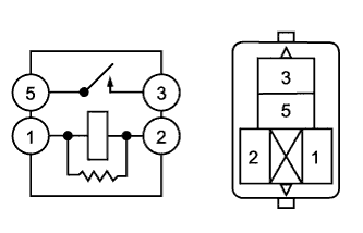
Measure the resistance according to the value(s) in the table below.
Standard Resistance Tester Connection Condition Specified Condition 1 - 2 Always 93.8 to 136.4 Ω 3 - 5 When battery voltage is not applied to terminals 1 and 2 10 kΩ or higher 3 - 5 When battery voltage is applied to terminals 1 and 2 Below 1 Ω
NG
REPLACE ST RELAY
OK
-
-
INSPECT PARK/NEUTRAL POSITION SWITCH ASSEMBLY
-
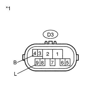
Text in Illustration *1 Component without harness connected
(Park/Neutral Position Switch Assembly)
for U660E, K112
-
Disconnect the D3 connector from the park/neutral position switch assembly.
-
Measure the resistance according to the value(s) in the table below.
Standard Resistance Tester Connection Condition Specified Condition D3-4 (B) - D3-9 (L) P or N Below 1 Ω D3-4 (B) - Body ground Always 10 kΩ or higher -
-
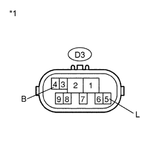
Text in Illustration *1 Component without harness connected
(Park/Neutral Position Switch Assembly)
for U241E
-
Disconnect the D3 connector from the park/neutral position switch assembly.
-
Measure the resistance according to the value(s) in the table below.
Standard Resistance Tester Connection Condition Specified Condition D3-4 (B) - D3-5 (L) P or N Below 1 Ω D3-4 (B) - Body ground Always 10 kΩ or higher Result Result Proceed to OK A NG (for U660E) B NG (for K112) C NG (for U241E) D -
B
REPLACE PARK/NEUTRAL POSITION SWITCH ASSEMBLY (for U660E) Click here
C
REPLACE PARK/NEUTRAL POSITION SWITCH ASSEMBLY (for K112) Click here
D
REPLACE PARK/NEUTRAL POSITION SWITCH ASSEMBLY (for U241E) Click here
A
-
-
CHECK HARNESS AND CONNECTOR (MAIN BODY ECU - PARK/NEUTRAL POSITION SWITCH ASSEMBLY)
-
Disconnect the G48 connector from the main body ECU.
-
Measure the resistance according to the value(s) in the table below.
Standard Resistance Tester Connection Condition Specified Condition G48-8 (STR) - D3-4 (B) Always Below 1 Ω G48-8 (STR) - Body ground Always 10 kΩ or higher
NG
REPAIR OR REPLACE HARNESS OR CONNECTOR (MAIN BODY ECU - PARK/NEUTRAL POSITION SWITCH ASSEMBLY)
OK
-
-
CHECK HARNESS AND CONNECTOR (PARK/NEUTRAL POSITION SWITCH ASSEMBLY - ST RELAY)
-
for U660E, K112
-
Measure the resistance according to the value(s) in the table below.
Standard Resistance Tester Connection Condition Specified Condition D3-9 (L) - No. 1 engine room relay block ST relay terminal 1 Always Below 1 Ω D3-9 (L) - Body ground Always 10 kΩ or higher
-
-
for U241E
-
Measure the resistance according to the value(s) in the table below.
Standard Resistance Tester Connection Condition Specified Condition D3-5 (L) - No. 1 engine room relay block ST relay terminal 1 Always Below 1 Ω D3-5 (L) - Body ground Always 10 kΩ or higher
-
NG
REPAIR OR REPLACE HARNESS OR CONNECTOR (PARK/NEUTRAL POSITION SWITCH ASSEMBLY - ST RELAY)
OK
REPLACE MAIN BODY ECU Click here
-