DESCRIPTION
The main body ECU receives brake signal information from 2 sources. It receives a signal from the stop light switch assembly via a direct line, and a signal from the ECM via CAN. If the information from these 2 sources is inconsistent, this DTC will be stored.
When the main body ECU is replaced with a new one and the cable from the negative (-) battery terminal is connected, the power source mode becomes IG-ON mode. When the battery is removed and reinstalled, the power source mode that was selected when the battery was removed is restored.
| DTC No. | DTC Detection Condition | Trouble Area |
|---|---|---|
| B2284 | Stop light switch assembly operation information received by the main body ECU from the stop light switch assembly via a direct line and stop light switch assembly information from the ECM via CAN are inconsistent. |
|
INSPECTION PROCEDURE
Inspect the fuses for circuits related to this system before performing the following inspection procedure.
Check the connector connections and terminals to make sure that there are no abnormalities such as loose connections, deformation, etc.
PROCEDURE
- Click here
CHECK CAN COMMUNICATION SYSTEM
-
Clear the DTCs (Click here).
-
Check if CAN communication system DTCs are output.
Tip:If any DTCs for the CAN communications system are output, inspect those DTCs first.
OK CAN communication DTCs are not output.
- OKClick here
- NGClick here
-
- Click here
CHECK FOR DTC (SFI SYSTEM)
-
Check if SFI system DTCs are output (Click here).
Tip:If any DTCs for the SFI system are output, inspect those DTCs first.
Result Result Proceed to SFI system DTCs are not output A SFI system DTCs are output (for 2GR-FE) B SFI system DTCs are output (for 2AZ-FE) C
-
- Click here
READ VALUE USING INTELLIGENT TESTER
-
Connect the intelligent tester to the DLC3.
-
Turn the engine switch on (IG).
-
Turn the intelligent tester on.
-
Enter the following menus: Body / Main Body / Data List.
-
Read the Data List according to the display on the intelligent tester.
Table 1. Main Body Tester Display Measurement Item/Range Normal Condition Diagnostic Note Stop Light Switch1 Stop light switch1 / ON or OFF ON: Brake pedal depressed
OFF: Brake pedal released
- OK ON (brake pedal depressed) and OFF (brake pedal released) appear on the screen.
- OKClick here
- NGClick here
-
- Click here
REPLACE MAIN BODY ECU
-
Replace the main body ECU (Click here).
- NEXTClick here
-
- Click here
CHECK FOR DTC
-
Clear the DTCs (Click here).
-
Check for DTCs again.
Result Result Proceed to SFI system DTCs are not output A SFI system DTCs are output (for 2GR-FE) B SFI system DTCs are output (for 2AZ-FE) C
-
- Click here
INSPECT STOP LIGHT SWITCH ASSEMBLY
-
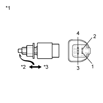
Disconnect the A1 connector from the stop light switch assembly.
-
Measure the resistance according to the value(s) in the table below.
Standard Resistance Tester Connection Condition Specified Condition 1 - 2 Pushed 10 kΩ or higher 1 - 2 Not pushed Below 1 Ω Table 2. Text in Illustration *1 Component without harness connected
(Stop Light Switch Assembly)
*2 Not Pushed (Free) *3 Pushed
- OKClick here
- NGClick here
-
- Click here
CHECK HARNESS AND CONNECTOR (STOP LIGHT SWITCH ASSEMBLY - MAIN BODY ECU)
-
Disconnect the 4K connector from the main body ECU.
-
Measure the resistance according to the value(s) in the table below.
Standard Resistance Tester Connection Condition Specified Condition 4K-7 (STP) - A1-1 Always Below 1 Ω 4K-7 (STP) - Body ground Always 10 kΩ or higher
- OKClick here
- NGClick here
-
- Click here
CHECK HARNESS AND CONNECTOR (BATTERY - STOP LIGHT SWITCH ASSEMBLY)
-
Reconnect the A1 connector to the stop light switch assembly.
-
Measure the voltage according to the value(s) in the table below.
Standard Voltage Tester Connection Condition Specified Condition 4K-7 (STP) - Body ground Brake pedal depressed 11 to 14 V 4K-7 (STP) - Body ground Brake pedal released Below 1 V
- OKClick here
- NGClick here
-
- Click here
GO TO CAN COMMUNICATION SYSTEMClick here
- Click here
GO TO SFI SYSTEM (for 2GR-FE)Click here
- Click here
GO TO SFI SYSTEM (for 2AZ-FE)Click here
- Click here
REPLACE ECM (for 2GR-FE)Click here
- Click here
REPLACE ECM (for 2AZ-FE)Click here
- Click here
END (MAIN BODY ECU WAS DEFECTIVE)
- Click here
REPLACE STOP LIGHT SWITCH ASSEMBLYClick here
- Click here
REPAIR OR REPLACE HARNESS OR CONNECTOR (STOP LIGHT SWITCH ASSEMBLY - MAIN BODY ECU)
- Click here
REPAIR OR REPLACE HARNESS OR CONNECTOR (BATTERY - STOP LIGHT SWITCH ASSEMBLY)
- Click here
REPLACE MAIN BODY ECUClick here