SMART ENTRY AND START SYSTEM (for Start Function), Diagnostic DTC:B2282

| DTC Code | DTC Name |
|---|---|
| B2282 | Vehicle Speed Signal Malfunction |
DESCRIPTION
The main body ECU receives vehicle speed information using 2 methods. It receives a speed signal from the combination meter assembly. It also receives speed information from the combination meter assembly via CAN. If the information sent using these 2 methods is inconsistent, this DTC will be stored.
Tech Tips
When the main body ECU is replaced with a new one and the negative (-) battery terminal is connected, the power source mode becomes IG-ON mode. When the battery is removed and reinstalled, the power source mode that was selected when the battery was removed is restored.
| DTC No. | DTC Detection Condition | Trouble Area |
|---|---|---|
| B2282 | The speed information received by the main body ECU from the combination meter assembly via a direct line and via CAN is inconsistent. |
|
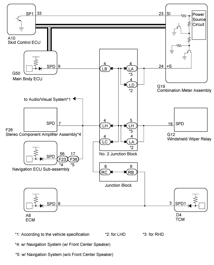
WIRING DIAGRAM
-
for 2GR-FE
-
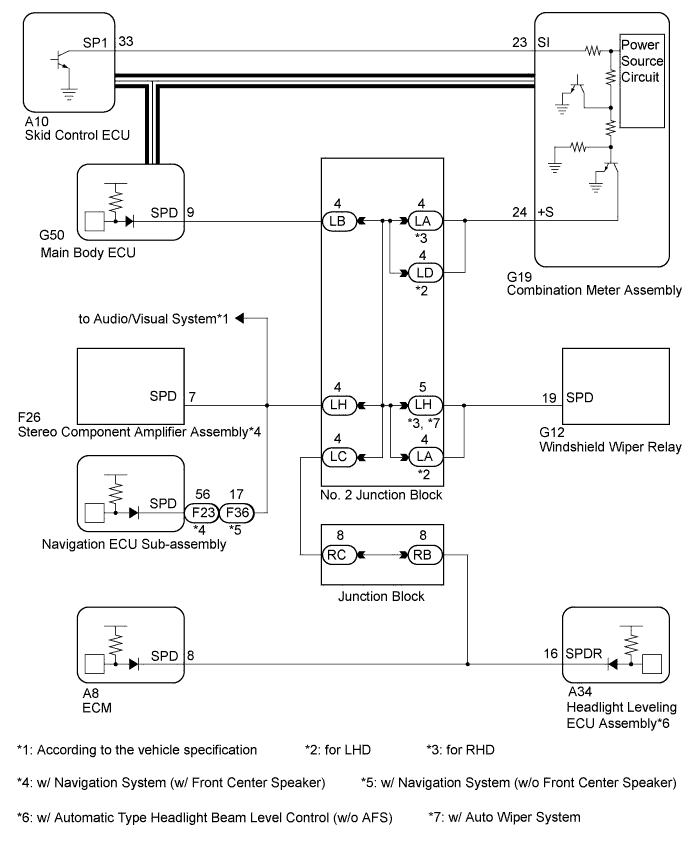
for 2AZ-FE
Tech Tips
-
A voltage of 12 V or 5 V is output from each ECU and then input to the combination meter. The signal is changed to a pulse signal at the transistor in the combination meter. Each ECU controls the respective system based on the pulse signal.
-
If a short occurs in an ECU, all systems in the wiring diagram will not operate normally.
-
INSPECTION PROCEDURE
PROCEDURE
-
CHECK CAN COMMUNICATION SYSTEM
-
Check if CAN communication DTCs are output.
Tech Tips
If DTCs for the CAN communication system are output, inspect those DTCs first.
OK CAN communication DTCs are not output.
NG 
GO TO CAN COMMUNICATION SYSTEM Click here
OK 
-
-
CHECK SPEEDOMETER OPERATION
-
Connect the intelligent tester to the DLC3.
-
Turn the engine switch on (IG).
-
Turn the intelligent tester on.
-
Enter the following menus: Body / Combination Meter / Data List.
-
Check the Data List for proper functioning of the vehicle speed signal.
Combination Meter Tester Display Measurement Item/Range Normal Condition Diagnostic Note Vehicle Speed Meter Vehicle speed/Min.: 0 km/h (0 mph), Max.: 255 km//h (158 mph) Almost same as actual speed (When driving) - OK Vehicle speed displayed on the intelligent tester is almost the same as the actual vehicle speed.
NG
GO TO METER/GAUGE SYSTEM (Speedometer Malfunction) Click here
OK
-
-
READ VALUE USING INTELLIGENT TESTER (VEHICLE SPEED SIGNAL)
-
Enter the following menus: Body / Main Body / Data List.
-
Read the Data List according to the display on the intelligent tester.
Main Body Tester Display Measurement Item/Range Normal Condition Specified Condition Vehicle speed signal Vehicle speed signal / Stop or Run Stop: Vehicle stopped
Run: Vehicle running
- OK Stop (vehicle is stopped) and Run (vehicle is running) appear on the screen.
NG 
CHECK HARNESS AND CONNECTOR (COMBINATION METER - MAIN BODY ECU) Click here
OK 
REPLACE MAIN BODY ECU Click here
-
-
CHECK HARNESS AND CONNECTOR (COMBINATION METER - MAIN BODY ECU)
-
Disconnect the G19 connector from the combination meter.
-
Disconnect the G50 connector from the main body ECU.
-
Measure the resistance according to the value(s) in the table below.
Standard Resistance Tester Connection Condition Specified Condition G19-24 (+S) - G50-9 (SPD) Always Below 1 Ω G19-24 (+S) - Body ground Always 10 kΩ or higher
NG
CHECK HARNESS AND CONNECTOR (COMBINATION METER - NO. 2 JUNCTION BLOCK) Click here
OK
-
-
INSPECT COMBINATION METER ASSEMBLY
-
Remove the combination meter Click here.
-
Reconnect the G19 connector to the combination meter.
-
Reconnect the G50 connector to the main body ECU.
-
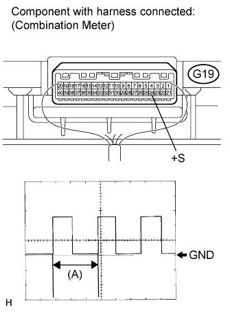
Connect an oscilloscope to terminal G19-24 (+S) and body ground.
-
Turn the engine switch on (IG).
-
Turn the wheel slowly.
-
Check the signal waveform according to the condition(s) in the table below.
Item Condition Tool setting 5 V/DIV., 20 ms./DIV. Vehicle condition Driving at approx. 20 km/h (12 mph) OK The waveform is displayed as shown in the illustration. Tech Tips
When the system is functioning normally, one wheel revolution generates 4 pulses. As the vehicle speed increases, the width indicated by (A) in the illustration narrows.
NG
GO TO METER / GAUGE SYSTEM (Speed Signal Circuit) Click here
OK
REPLACE MAIN BODY ECU Click here
-
-
CHECK HARNESS AND CONNECTOR (COMBINATION METER - NO. 2 JUNCTION BLOCK)
-
Disconnect the LA to LD No. 2 junction block connector.
-
Measure the resistance according to the value(s) in the table below.
Standard Resistance Tester Connection Condition Specified Condition G19-24 (+S) - LA-4*1 Always Below 1 Ω G19-24 (+S) - LD-4*2 Always Below 1 Ω G19-24 (+S) - Body ground Always 10 kΩ or higher
-
*1: for RHD
-
*2: for LHD
-
NG
REPAIR OR REPLACE HARNESS OR CONNECTOR (COMBINATION METER - NO. 2 JUNCTION BLOCK)
OK
-
-
CHECK HARNESS AND CONNECTOR (MAN BODY ECU - NO. 2 JUNCTION BLOCK)
-
Measure the resistance according to the value(s) in the table below.
Standard Resistance Tester Connection Condition Specified Condition G50-9 (SPD) - LB-4 Always Below 1 Ω G50-9 (SPD) - Body ground Always 10 kΩ or higher
NG
REPAIR OR REPLACE HARNESS OR CONNECTOR (PASSENGER SIDE JUNCTION BLOCK - NO. 2 JUNCTION BLOCK)
OK
REPLACE NO. 2 JUNCTION BLOCK
-