SMART ENTRY AND START SYSTEM (for Start Function), Diagnostic DTC:B2281

| DTC Code | DTC Name |
|---|---|
| B2281 | "P" Signal Malfunction |
DESCRIPTION
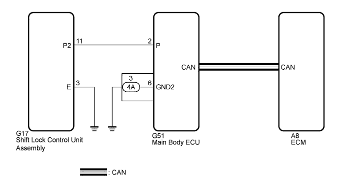
The main body ECU receives shift position information from 2 sources. It receives a shift position P signal from the shift lock control unit assembly via a direct line, and shift position information from the ECM via CAN. If the information from these 2 sources is inconsistent, this DTC will be stored.
Tech Tips
When the main body ECU is replaced with a new one and the cable from the negative (-) battery terminal is connected, the power source mode becomes IG-ON mode. When the battery is removed and reinstalled, the power source mode that was selected when the battery was removed is restored.
| DTC No. | DTC Detection Condition | Trouble Area |
|---|---|---|
| B2281 | The shift position information from the ECM (via CAN) and the shift lock control unit assembly (direct line) is inconsistent. |
|
WIRING DIAGRAM
INSPECTION PROCEDURE
PROCEDURE
-
CHECK CAN COMMUNICATION SYSTEM
-
Clear the DTCs Click here.
-
Check if CAN communication system DTCs are output.
Tech Tips
If DTCs for the CAN communication system are output, inspect those DTCs first.
OK CAN communication system DTC is not output.
NG 
GO TO CAN COMMUNICATION SYSTEM Click here
OK 
-
-
CHECK FOR DTC (SFI SYSTEM)
-
Check if SFI system DTCs are output Click here.
Tech Tips
If DTCs for the SFI system are output, inspect those DTCs first.
Result Result Proceed to SFI DTCs are not output A SFI DTCs are output (for 2GR-FE) B SFI DTCs are output (for 2AZ-FE) C
B
GO TO SFI SYSTEM (for 2GR-FE) Click here
C
GO TO SFI SYSTEM (for 2AZ-FE) Click here
A
-
-
READ VALUE USING INTELLIGENT TESTER
-
Connect the intelligent tester to the DLC3.
-
Turn the engine switch on (IG).
-
Turn the intelligent tester on.
-
Enter the following menus: Body / Main Body / Data List.
-
Read the Data List according to the display on the intelligent tester.
Main Body Tester Display Measurement Item/Range Normal Condition Diagnostic Note Shift P Signal Shift P position/ON or OFF ON: Shift lever in P
OFF: Shift lever not in P
- OK ON (shift lever in P) and OFF (shift lever not in P) appear on the screen.
NG 
CHECK SHIFT LOCK CONTROL UNIT ASSEMBLY Click here
OK
-
-
CHECK PARK/NEUTRAL POSITION SWITCH ASSEMBLY
-
Check the park/neutral position switch assembly installation condition (for 2GR-FE: Click here, for 2AZ-FE (U660E): Click here, 2AZ-FE (U241E): Click here.
NEXT
-
-
REPLACE MAIN BODY ECU
-
Replace the main body ECU Click here.
NEXT
-
-
CHECK FOR DTC
-
Clear the DTCs Click here.
-
Check if DTC B2281 is output.
Result Result Proceed to DTC B2281 is not output A DTC B2281 is output (for 2GR-FE) B DTC B2281 is output (for 2AZ-FE) C
B
REPLACE ECM (for 2GR-FE) Click here
C
REPLACE ECM (for 2AZ-FE) Click here
A 
END (MAIN BODY ECU WAS DEFECTIVE)
-
-
CHECK SHIFT LOCK CONTROL UNIT ASSEMBLY
-
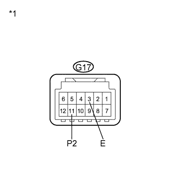
Text in Illustration *1 Component without harness connected
(Shift Lock Control Unit Assembly)
Disconnect the G17 connector from the shift lock control unit assembly.
-
Measure the resistance according to the value(s) in the table below.
Standard Resistance Tester Connection Condition Specified Condition G17-11 (P2) - G17-3 (E) Shift lever in P Below 1 Ω G17-11 (P2) - G17-3 (E) Shift lever not in P 10 kΩ or higher Result Result Proceed to OK A NG (for U660E) B NG (for U241E) C NG (for K112) D
B
REPLACE SHIFT LOCK CONTROL UNIT ASSEMBLY (for U660E) Click here
C
REPLACE SHIFT LOCK CONTROL UNIT ASSEMBLY (for U241E) Click here
C
REPLACE SHIFT LOCK CONTROL UNIT ASSEMBLY (for K112) Click here
A
-
-
CHECK HARNESS AND CONNECTOR (MAIN BODY ECU - SHIFT LOCK CONTROL UNIT ASSEMBLY)
-
Disconnect the G51 connector from the main body ECU.
-
Measure the resistance according to the value(s) in the table below.
Standard Resistance Tester Connection Condition Specified Condition G51-2 (P) - G17-11 (P2) Always Below 1 Ω G51-2 (P) - Body ground Always 10 kΩ or higher G17-3 (E) - Body ground Always Below 1 Ω
NG
REPAIR OR REPLACE HARNESS OR CONNECTOR (MAIN BODY ECU - SHIFT LOCK CONTROL UNIT ASSEMBLY)
OK
REPLACE MAIN BODY ECU Click here
-