DESCRIPTION
This DTC is stored when there is an open, short, or any other problem in the engine start request output circuit inside the main body ECU or in the external circuit.
When the main body ECU is replaced with a new one and the cable from the negative (-) battery terminal is connected, the power source mode becomes IG-ON mode. When the battery is removed and reinstalled, the power source mode that was selected when the battery was removed is restored.
| DTC No. | DTC Detection Condition | Trouble Area |
|---|---|---|
| B2275 | The ST output circuit (engine starting request signal circuit) inside the main body ECU or other related circuit is malfunctioning |
|
INSPECTION PROCEDURE
PROCEDURE
- Click here
CHECK FOR DTC
-
Clear the DTCs (Click here).
-
Turn the engine switch on (IG).
-
After 15 seconds have elapsed, recheck for DTCs and check if the same DTC is output.
OK DTC B2275 is not output.
- OKClick here
- NGClick here
-
- Click here
CHECK HARNESS AND CONNECTOR (MAIN BODY ECU - ECM)
-
Disconnect the G51 connector from the main body ECU.
-
Disconnect the A8 connector from the ECM.
-
Measure the resistance according to the value(s) in the table below.
Standard Resistance Tester Connection Condition Specified Condition G51-4 (STSW) - A8-14 (STSW) Always Below 1 Ω G51-4 (STSW) - Body ground Always 10 kΩ or higher
- OKClick here
- NGClick here
-
- Click here
CHECK MAIN BODY ECU
-
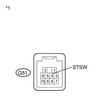
Reconnect the G51 connector to the main body ECU.
-
Measure the voltage according to the value(s) in the table below.
Standard Voltage Tester Connection Condition Specified Condition G51-4 (STSW) - Body ground Brake pedal depressed, Engine switch hold on (ST) Voltage at STSW is within 2 V of the voltage measured at AM1 or AM2*. Table 1. Text in Illustration *1 Component with harness connected
(Main Body ECU)
Tip:*: A maximum voltage drop of 2 V across the main body ECU is permitted.
Result Result Proceed to OK (for 2GR-FE) A OK (for 2AZ-FE) B NG C
-
- Click here
USE SIMULATION METHOD TO CHECKClick here
- Click here
REPAIR OR REPLACE HARNESS OR CONNECTOR (MAIN BODY ECU - ECM)
- Click here
REPLACE ECM (for 2AZ-FE)Click here
- Click here
REPLACE MAIN BODY ECUClick here
- Click here
REPLACE ECM (for 2GR-FE)Click here