SMART ENTRY AND START SYSTEM (for Start Function), Diagnostic DTC:B2276

| DTC Code | DTC Name |
|---|---|
| B2276 | ACCR Signal Circuit Malfunction |
DESCRIPTION
This DTC is stored when the ACCR output circuit inside the main body ECU is open or shorted.
Tech Tips
When the main body ECU is replaced with a new one and the cable from the negative (-) battery terminal is connected, the power source mode becomes IG-ON mode. When the battery is removed and reinstalled, the power source mode that was selected when the battery was removed is restored.
| DTC No. | DTC Detection Condition | Trouble Area |
|---|---|---|
| B2276 | The ACCR output circuit inside the main body ECU or other related circuit is malfunctioning. |
|
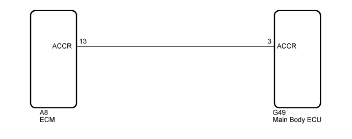
WIRING DIAGRAM
INSPECTION PROCEDURE
PROCEDURE
-
CHECK FOR DTC
-
Clear the DTCs Click here.
-
Turn the engine switch on (IG).
-
After 50 seconds have elapsed, recheck for DTCs and check if the same DTC is output.
OK DTC B2276 is not output.
NG 
CHECK HARNESS AND CONNECTOR (MAIN BODY ECU - ECM) Click here
OK 
USE SIMULATION METHOD TO CHECK Click here
-
-
CHECK HARNESS AND CONNECTOR (MAIN BODY ECU - ECM)
-
Disconnect the G49 connector from the main body ECU.
-
Disconnect the A8 connector from the ECM.
-
Measure the resistance according to the value(s) in the table below.
Standard Resistance Tester Connection Condition Specified Condition G49-3 (ACCR) - A8-13 (ACCR) Always Below 1 Ω G49-3 (ACCR) - Body ground Always 10 kΩ or higher
NG 
REPAIR OR REPLACE HARNESS OR CONNECTOR (MAIN BODY ECU - ECM)
OK 
-
-
CHECK MAIN BODY ECU
-
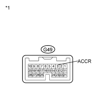
Text in Illustration *1 Component with harness connected
(Main Body ECU)
Reconnect the G49 connector to the main body ECU.
-
Reconnect the A8 connector to the ECM.
-
Measure the voltage according to the value(s) in the table below.
Standard Voltage Tester Connection Condition Specified Condition G49-3 (ACCR) - Body ground Brake pedal depressed, shift lever in P, engine switch is pushed once → on (IG) 0.1 to 0.8 V → Output voltage is within 2 V of the voltage measured at AM1 or AM2*. Tech Tips
*: Voltage is output only when the engine is cranking.
Result Result Proceed to OK A NG (for 2GR-FE) B NG (for 2AZ-FE) C
B
REPLACE ECM (for 2GR-FE) Click here
C
REPLACE ECM (for 2AZ-FE) Click here
A
REPLACE MAIN BODY ECU Click here
-