CAN COMMUNICATION SYSTEM Check CAN Bus Lines for Short Circuit (RHD Models)
DESCRIPTION
There may be a short circuit between the CAN bus main wires and/or CAN branch wires when the resistance between terminals 6 (CANH) and 14 (CANL) of the DLC3 is below 54 Ω.
| Symptom | Trouble Area |
|---|---|
| Resistance between terminals 6 (CANH) and 14 (CANL) of DLC3 is below 54 Ω. |
|
Tech Tips
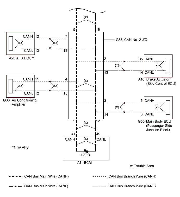
*1: w/ AFS
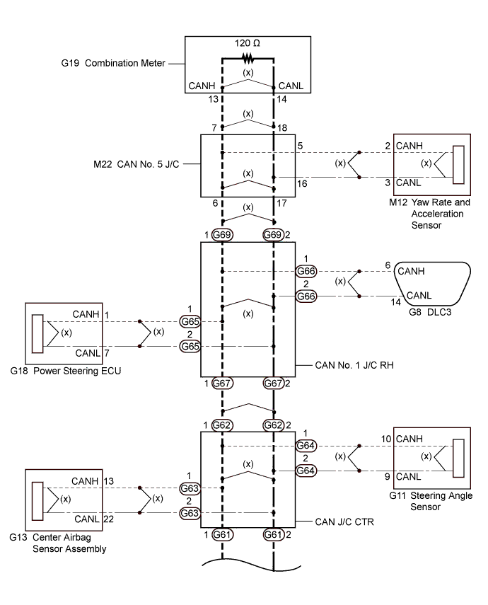
WIRING DIAGRAM
INSPECTION PROCEDURE
Note
-
Turn the engine switch off before measuring the resistances of the CAN main wires and the CAN branch wires.
-
After the engine switch is turned off, check that the key reminder warning system and light reminder warning system are not in operation.
-
Before measuring the resistance, leave the vehicle as is for at least 1 minute and do not operate the engine switch, any other switches or doors. If any doors need to be opened in order to check the connectors, open the doors and leave them open.
Tech Tips
-
Operating the engine switch, any other switches or a door triggers related ECU and sensor communication on the CAN. This communication will cause the resistance value to change.
-
Even after DTCs are cleared, if a DTC is stored again after driving the vehicle for a while, the malfunction may be occurring due to vibration of the vehicle. In such a case, wiggling the ECUs or wire harness while performing the inspection below will help determine the cause of the malfunction.
PROCEDURE
-
CHECK FOR SHORT IN CAN BUS WIRE (DLC3 BRANCH WIRE)
-
Turn the engine switch off.
-
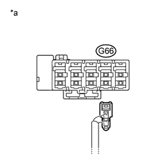
Text in Illustration *a Rear view of wire harness connector
(to CAN No. 1 Junction Connector RH)
Disconnect the CAN branch wire connector (G66) from the CAN No. 1 junction connector RH (w/o earth terminal).
Note
-
Before disconnecting the connector, make a note of where it is connected.
-
Reconnect the connector to its original position.
-
-
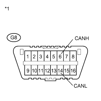
Text in Illustration *1 DLC3 Measure the resistance according to the value(s) in the table below.
Standard Resistance Tester Connection Switch Condition Specified Condition G8-6 (CANH) - G8-14 (CANL) Engine switch off 1 MΩ or higher
NG 
REPAIR OR REPLACE CAN BRANCH WIRE CONNECTED TO DLC3
OK 
-
-
CHECK FOR SHORT IN CAN BUS WIRE (CAN NO. 1 J/C RH - CAN NO. 5 J/C)
-
Reconnect the CAN branch wire connector (G66) to the CAN No. 1 junction connector RH (w/o earth terminal).
-
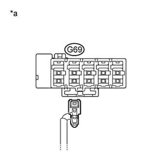
Text in Illustration *a Rear view of wire harness connector
(to CAN No. 1 Junction Connector RH)
Disconnect the CAN main wire connector (G69) from the CAN No. 1 junction connector RH (w/o earth terminal).
Note
-
Before disconnecting the connector, make a note of where it is connected.
-
Reconnect the connector to its original position.
-
-
Text in Illustration *1 DLC3 Measure the resistance according to the value(s) in the table below.
Standard Resistance Tester Connection Switch Condition Specified Condition G8-6 (CANH) - G8-14 (CANL) Engine switch off 108 to 132 Ω Result Result Proceed to The resistance is still below 54 Ω when the specified connector is disconnected. (There is a short in the bus wires.) A The resistance becomes normal (between 108 to 132 Ω) when a connector is disconnected. (There is a short in the disconnected bus wires.) B
B 
CHECK FOR SHORT IN CAN BUS WIRE (CAN NO. 1 J/C RH - CAN NO. 5 J/C) Click here
A
-
-
CHECK FOR SHORT IN CAN BUS WIRE (CAN NO. 1 J/C RH - CAN J/C CTR)
-
Reconnect the CAN main wire connector (G69) to the CAN No. 1 junction connector RH (w/o earth terminal).
-
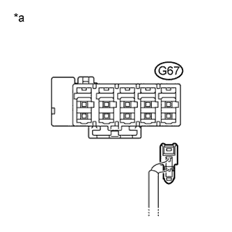
Text in Illustration *a Rear view of wire harness connector
(to CAN No. 1 Junction Connector RH)
Disconnect the CAN main wire connector (G67) from the CAN No. 1 junction connector RH (w/o earth terminal).
Note
-
Before disconnecting the connector, make a note of where it is connected.
-
Reconnect the connector to its original position.
-
-
Text in Illustration *1 DLC3 Measure the resistance according to the value(s) in the table below.
Standard Resistance Tester Connection Switch Condition Specified Condition G8-6 (CANH) - G8-14 (CANL) Engine switch off 108 to 132 Ω Result Result Proceed to The resistance is still below 54 Ω when the specified connector is disconnected. (There is a short in the bus wires.) A The resistance becomes normal (between 108 to 132 Ω) when a connector is disconnected. (There is a short in the disconnected bus wires.) B
B
CHECK FOR SHORT IN CAN BUS WIRE (CAN NO. 1 J/C RH - CAN J/C CTR) Click here
A
-
-
CHECK FOR SHORT IN CAN BUS WIRE (CAN NO. 1 J/C RH)
-
Text in Illustration *1 DLC3 Connect the probes of an ohmmeter to terminals CANH and CANL of the DLC3.
-
While observing the resistance value shown on the tester, disconnect connector (G65) from the CAN No. 1 junction connector RH one by one until the resistance becomes normal (between 54 and 69 Ω).
Tech Tips
Disconnect the branch wire connectors other than those of the DLC3.
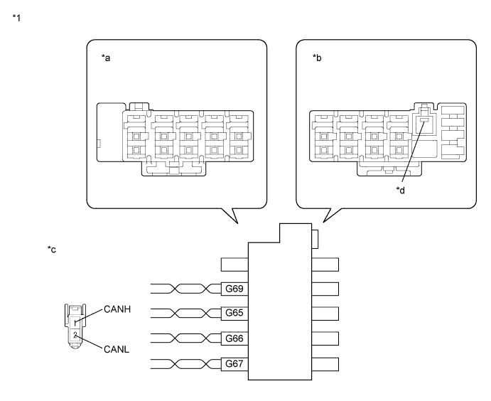
for CAN Junction Connector B Side Terminal No. (Symbol) Wiring Color Connected to G65-1 (CANH) SB Power steering ECU G65-2 (CANL) W G66-1 (CANH) GR DLC3 G66-2 (CANL) W G67-1 (CANH) SB CAN junction connector CTR G67-2 (CANL) W G69-1 (CANH) B CAN No. 5 junction connector G69-2 (CANL) W Text in Illustration *1 CAN No. 1 Junction Connector RH - - *a Junction Connector B Side *b Junction Connector A Side *c Front view of wire harness connector
(to CAN No. 1 Junction Connector RH)
*d Earth Terminal Note
Do not reconnect the disconnected connectors until this inspection is complete because there may be a short in 2 or more branch wires.
Result Result Proceed to The resistance is still below 54 Ω when all the specified connectors are disconnected. (There is no short in the branch wires.) A The resistance becomes normal (between 54 and 69 Ω) when a connector is disconnected. (There is a short in one or more of the branch wires.) B -
When there is a short in one or more of the branch wires:
-
Reconnect all of the connectors to the CAN junction connector, except for the one that was disconnected last (the short-circuited bus wire). Check that the resistance shown on the tester becomes normal (between 54 and 69 Ω) to confirm that there is a short in the only one branch wire.
Tech Tips
-
The shape of connectors connected to the CAN junction connector which has an earth terminal is the same. The connectors connected to the CAN junction connector can be distinguished by the colors of the bus wire and the connecting side of the junction connector.
-
Reconnecting the connectors to non-specified positions on the CAN junction connector does not affect system operation. However, it is preferred to reconnect the connectors to their specified positions to avoid negative effects on the wiring such as tension on the wiring harnesses, and to make future maintenance easier.
-
-
B
CHECK FOR SHORT IN CAN BUS WIRE Click here
A 
REPLACE CAN NO. 1 JUNCTION CONNECTOR RH
-
-
CHECK FOR SHORT IN CAN BUS WIRE
-
Reconnect the CAN main wire connector (G67) to the CAN No. 1 junction connector RH (w/o earth terminal).
-
Reconnect the CAN main wire connector (G69) to the CAN No. 1 junction connector RH (w/o earth terminal).
-
Reconnect the connector for the short-circuited branch wire to the CAN junction connector (the connector that caused the bus wire resistance to become normal (between 54 and 69 Ω) when it was disconnected).
-
Disconnect the connector that includes terminals CANH and CANL from the ECU to which the short-circuited branch wire is connected.
-
Text in Illustration *1 DLC3 Measure the resistance according to the value(s) in the table below.
Standard Resistance Tester Connection Switch Condition Specified Condition G8-6 (CANH) - G8-14 (CANL) Engine switch off 54 to 69 Ω Tech Tips
If the resistance becomes normal (between 54 and 69 Ω) when the connector is disconnected from the ECU, there may be a short in the ECU.
NG
REPAIR OR REPLACE CORRESPONDING ECU BRANCH WIRE OR CONNECTOR
OK
REPLACE CORRESPONDING ECU
-
-
CHECK FOR SHORT IN CAN BUS WIRE (CAN NO. 1 J/C RH - CAN NO. 5 J/C)
-
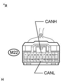
Text in Illustration *a Front view of wire harness connector
(to CAN No. 5 Junction Connector)
Disconnect the connector of the CAN No. 5 junction connector.
-
Measure the resistance according to the value(s) in the table below.
Standard Resistance Tester Connection Switch Condition Specified Condition M22-6 (CANH) - M22-17 (CANL) Engine switch off 1 MΩ or higher
NG
REPAIR OR REPLACE CAN BUS MAIN WIRE OR CONNECTOR (CAN NO. 1 J/C RH - CAN NO. 5 J/C)
OK
-
-
CHECK FOR SHORT IN CAN BUS WIRE (CAN NO. 5 J/C - COMBINATION METER)
-
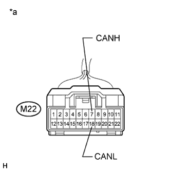
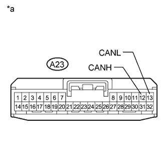
Text in Illustration *a Front view of wire harness connector
(to CAN No. 5 Junction Connector)
Measure the resistance according to the value(s) in the table below.
Standard Resistance Tester Connection Switch Condition Specified Condition M22-7 (CANH) - M22-18 (CANL) Engine switch off 108 to 132 Ω
NG
CHECK FOR SHORT IN CAN BUS WIRE (COMBINATION METER) Click here
OK
-
-
CHECK FOR SHORT IN CAN BUS WIRE (CAN NO. 5 J/C - YAW RATE AND ACCELERATION SENSOR)
-
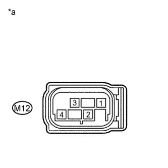
Text in Illustration *a Front view of wire harness connector
(to Yaw Rate and Acceleration Sensor)
Disconnect the connector of the yaw rate and acceleration sensor.
-
Text in Illustration *a Front view of wire harness connector
(to CAN No. 5 Junction Connector)
Measure the resistance according to the value(s) in the table below.
Standard Resistance Tester Connection Switch Condition Specified Condition M22-5 (CANH) - M22-16 (CANL) Engine switch off 1 MΩ or higher
NG
REPAIR OR REPLACE CAN BUS BRANCH WIRE OR CONNECTOR (CAN NO. 5 J/C - YAW RATE AND ACCELERATION SENSOR)
OK
-
-
CHECK FOR SHORT IN CAN BUS WIRE (YAW RATE AND ACCELERATION SENSOR)
-
Reconnect the CAN main wire connector (G69) to the CAN No. 1 junction connector RH (w/o earth terminal).
-
Reconnect the connector of the CAN No. 5 junction connector.
-
Text in Illustration *1 DLC3 Measure the resistance according to the value(s) in the table below.
Standard Resistance Tester Connection Switch Condition Specified Condition G8-6 (CANH) - G8-14 (CANL) Engine switch off 54 Ω or higher
NG
REPLACE CAN NO. 5 JUNCTION CONNECTOR
OK
REPLACE YAW RATE AND ACCELERATION SENSOR Click here
-
-
CHECK FOR SHORT IN CAN BUS WIRE (COMBINATION METER)
-
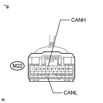
Text in Illustration *a Front view of wire harness connector
(to Combination Meter)
Disconnect the connector of the combination meter.
-
Text in Illustration *a Front view of wire harness connector
(to CAN No. 5 Junction Connector)
Measure the resistance according to the value(s) in the table below.
Standard Resistance Tester Connection Switch Condition Specified Condition M22-7 (CANH) - M22-18 (CANL) Engine switch off 1 MΩ or higher
NG
REPAIR OR REPLACE CAN BUS MAIN WIRE OR CONNECTOR (CAN NO. 5 J/C - COMBINATION METER)
OK
REPLACE COMBINATION METER Click here
-
-
CHECK FOR SHORT IN CAN BUS WIRE (CAN NO. 1 J/C RH - CAN J/C CTR)
-
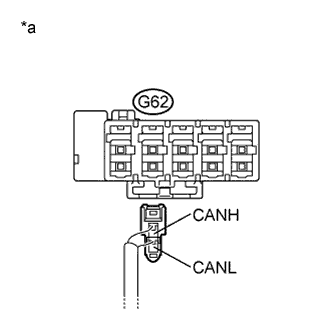
Text in Illustration *a Rear view of wire harness connector
(to CAN Junction Connector CTR)
Disconnect the CAN main wire connector (G62) from the CAN junction connector CTR (w/o earth terminal).
Note
-
Before disconnecting the connector, make a note of where it is connected.
-
Reconnect the connector to its original position.
-
-
Measure the resistance according to the value(s) in the table below.
Standard Resistance Tester Connection Switch Condition Specified Condition G62-1 (CANH) - G62-2 (CANL) Engine switch off 1 MΩ or higher
NG
REPAIR OR REPLACE CAN BUS MAIN WIRE OR CONNECTOR (CAN NO. 1 J/C RH - CAN J/C CTR)
OK
-
-
CHECK FOR SHORT IN CAN BUS WIRE (CAN J/C CTR - CAN NO. 2 J/C)
-
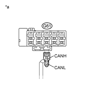
Text in Illustration *a Rear view of wire harness connector
(to CAN Junction Connector CTR)
Disconnect the CAN main wire connector (G61) from the CAN junction connector CTR (w/o earth terminal).
Note
-
Before disconnecting the connector, make a note of where it is connected.
-
Reconnect the connector to its original position.
-
-
Measure the resistance according to the value(s) in the table below.
Standard Resistance Tester Connection Switch Condition Specified Condition G61-1 (CANH) - G61-2 (CANL) Engine switch off 108 to 132 Ω
NG
CHECK FOR SHORT IN CAN BUS WIRE (CAN J/C CTR - CAN NO. 2 J/C) Click here
OK
-
-
CHECK FOR SHORT IN CAN BUS WIRE (CAN J/C CTR)
-
Text in Illustration *1 DLC3 Connect the probes of an ohmmeter to terminals CANH and CANL of the DLC3.
-
While observing the resistance value shown on the tester, disconnect connectors (G63 and G64) from the CAN junction connector CTR one by one until the resistance becomes normal (between 54 and 69 Ω).
Tech Tips
Disconnect the branch wire connectors other than those of the DLC3.
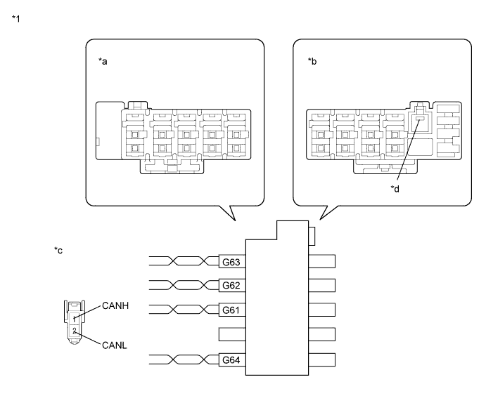
for CAN Junction Connector B Side Terminal No. (Symbol) Wiring Color Connected to G61-1 (CANH) B CAN No. 2 junction connector G61-2 (CANL) W G62-1 (CANH) SB CAN No. 1 junction connector RH G62-2 (CANL) W G63-1 (CANH) Y Center airbag sensor assembly G63-2 (CANL) W G64-1 (CANH) BR Steering angle sensor G64-2 (CANL) W Text in Illustration *1 CAN Junction Connector CTR - - *a Junction Connector B Side *b Junction Connector A Side *c Front view of wire harness connector
(to CAN Junction Connector CTR)
*d Earth Terminal Note
Do not reconnect the disconnected connectors until this inspection is complete because there may be a short in 2 or more branch wires.
Result Result Proceed to The resistance is still below 54 Ω when all the specified connectors are disconnected. (There is no short in the branch wires.) A The resistance becomes normal (between 54 and 69 Ω) when a connector is disconnected. (There is a short in one or more of the branch wires.) B -
When there is a short in one or more of the branch wires:
-
Reconnect all of the connectors to the CAN junction connector, except for the one that was disconnected last (the short-circuited bus wire). Check that the resistance shown on the tester becomes normal (between 54 and 69 Ω) to confirm that there is a short in the only one branch wire.
Tech Tips
-
The shape of connectors connected to the CAN junction connector which has an earth terminal is the same. The connectors connected to the CAN junction connector can be distinguished by the colors of the bus wire and the connecting side of the junction connector.
-
Reconnecting the connectors to non-specified positions on the CAN junction connector does not affect system operation. However, it is preferred to reconnect the connectors to their specified positions to avoid negative effects on the wiring such as tension on the wiring harnesses, and to make future maintenance easier.
-
-
B
CHECK FOR SHORT IN CAN BUS WIRE Click here
A
REPLACE CAN JUNCTION CONNECTOR CTR
-
-
CHECK FOR SHORT IN CAN BUS WIRE
-
Reconnect the CAN main wire connector (G61 and G62) to the CAN junction connector CTR (w/o earth terminal).
-
Reconnect the CAN main wire connector (G67) to the CAN No. 1 junction connector RH (w/o earth terminal).
-
Reconnect the connector of the short-circuited branch wire to the CAN junction connector (the connector that caused the bus wire resistance to become normal (between 54 and 69 Ω) when it was disconnected).
-
Disconnect the connector that includes terminals CANH and CANL from the ECU or sensor to which the short-circuited branch wire is connected.
-
Text in Illustration *1 DLC3 Measure the resistance according to the value(s) in the table below.
Standard Resistance Tester Connection Switch Condition Specified Condition G8-6 (CANH) - G8-14 (CANL) Engine switch off 54 to 69 Ω Tech Tips
If the resistance becomes normal (between 54 and 69 Ω) when the connector is disconnected from the ECU or sensor, there may be a short in the ECU or sensor.
NG
REPAIR OR REPLACE CORRESPONDING ECU OR SENSOR BRANCH WIRE OR CONNECTOR
OK
REPLACE CORRESPONDING ECU OR SENSOR
-
-
CHECK FOR SHORT IN CAN BUS WIRE (CAN J/C CTR - CAN NO. 2 J/C)
-
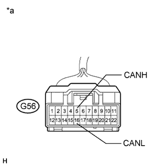
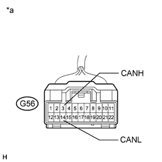
Text in Illustration *a Front view of wire harness connector
(to CAN No. 2 Junction Connector)
Disconnect the connector of the CAN No. 2 junction connector.
-
Measure the resistance according to the value(s) in the table below.
Standard Resistance Tester Connection Switch Condition Specified Condition G56-5 (CANH) - G56-16 (CANL) Engine switch off 1 MΩ or higher
NG
REPAIR OR REPLACE CAN BUS MAIN WIRE OR CONNECTOR (CAN J/C CTR - CAN NO. 2 J/C)
OK
-
-
CHECK FOR SHORT IN CAN BUS WIRE (CAN NO. 2 J/C - ECM)
-
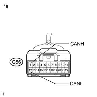
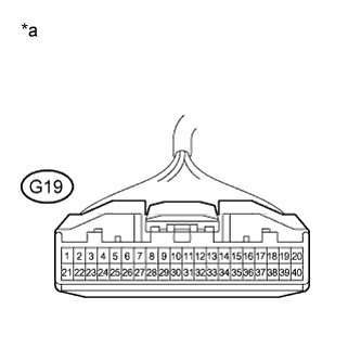
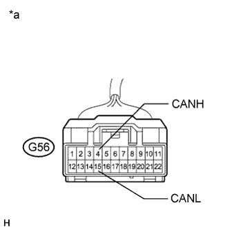
Text in Illustration *a Front view of wire harness connector
(to CAN No. 2 Junction Connector)
Measure the resistance according to the value(s) in the table below.
Standard Resistance Tester Connection Switch Condition Specified Condition G56-1 (CANH) - G56-12 (CANL) Engine switch off 108 to 132 Ω
NG
CHECK FOR SHORT IN CAN BUS WIRE (ECM) Click here
OK
-
-
CHECK FOR SHORT IN CAN BUS WIRE (CAN NO. 2 J/C - SKID CONTROL ECU)
-
Text in Illustration *a Front view of wire harness connector
(to Skid Control ECU)
Disconnect the connector of the skid control ECU.
-
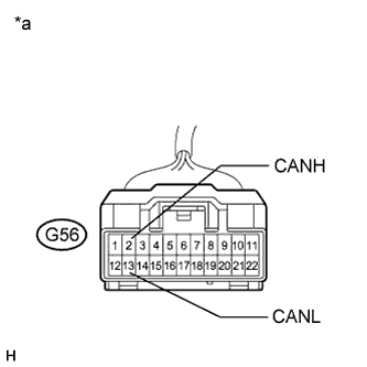
Text in Illustration *a Front view of wire harness connector
(to CAN No. 2 Junction Connector)
Measure the resistance according to the value(s) in the table below.
Standard Resistance Tester Connection Switch Condition Specified Condition G56-2 (CANH) - G56-13 (CANL) Engine switch off 1 MΩ or higher
NG
REPAIR OR REPLACE CAN BUS BRANCH WIRE OR CONNECTOR (CAN NO. 2 J/C - SKID CONTROL ECU)
OK
-
-
CHECK FOR SHORT IN CAN BUS WIRE (SKID CONTROL ECU)
-
Reconnect the CAN main wire connector (G67) to the CAN No. 1 junction connector RH (w/o earth terminal).
-
Reconnect the CAN main wire connectors (G61 and G62) to the CAN junction connector CTR (w/o earth terminal).
-
Reconnect the connector of the CAN No. 2 junction connector.
-
Text in Illustration *1 DLC3 Measure the resistance according to the value(s) in the table below.
Standard Resistance Tester Connection Switch Condition Specified Condition G8-6 (CANH) - G8-14 (CANL) Engine switch off 54 Ω or higher
NG
CHECK FOR SHORT IN CAN BUS WIRE (CAN NO. 2 J/C - AIR CONDITIONING AMPLIFIER) Click here
OK
REPLACE BRAKE ACTUATOR (SKID CONTROL ECU) Click here
-
-
CHECK FOR SHORT IN CAN BUS WIRE (CAN NO. 2 J/C - AIR CONDITIONING AMPLIFIER)
-
Disconnect the connector of the CAN No. 2 junction connector.
-
Text in Illustration *a Front view of wire harness connector
(to Air Conditioning Amplifier)
Disconnect the connector of the air conditioning amplifier.
-
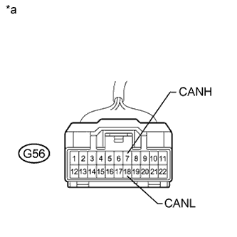
Text in Illustration *a Front view of wire harness connector
(to CAN No. 2 Junction Connector)
Measure the resistance according to the value(s) in the table below.
Standard Resistance Tester Connection Switch Condition Specified Condition G56-4 (CANH) - G56-15 (CANL) Engine switch off 1 MΩ or higher
NG
REPAIR OR REPLACE CAN BUS BRANCH WIRE OR CONNECTOR (CAN NO. 2 J/C - AIR CONDITIONING AMPLIFIER)
OK
-
-
CHECK FOR SHORT IN CAN BUS WIRE (AIR CONDITIONING AMPLIFIER)
-
Reconnect the connector of the CAN No. 2 junction connector.
-
Text in Illustration *1 DLC3 Measure the resistance according to the value(s) in the table below.
Standard Resistance Tester Connection Switch Condition Specified Condition G8-6 (CANH) - G8-14 (CANL) Engine switch off 54 to 69 Ω
NG
CHECK FOR SHORT IN CAN BUS WIRE (CAN NO. 2 J/C - AFS ECU) Click here
OK
REPLACE AIR CONDITIONING AMPLIFIER Click here
-
-
CHECK FOR SHORT IN CAN BUS WIRE (CAN NO. 2 J/C - AFS ECU)
Tech Tips
For vehicles without a headlight swivel ECU (AFS ECU), go to "CHECK FOR SHORT IN CAN BUS WIRE (CAN NO. 2 J/C - MAIN BODY ECU)".
-
Disconnect the connector of the CAN No. 2 junction connector.
-
Text in Illustration *a Front view of wire harness connector
(to Headlight Swivel ECU)
Disconnect the connector of the headlight swivel ECU (AFS ECU).
-
Text in Illustration *a Front view of wire harness connector
(to CAN No. 2 Junction Connector)
Measure the resistance according to the value(s) in the table below.
Standard Resistance Tester Connection Switch Condition Specified Condition G56-7 (CANH) - G56-18 (CANL) Engine switch off 1 MΩ or higher
NG
REPAIR OR REPLACE CAN BUS BRANCH WIRE OR CONNECTOR (CAN NO. 2 J/C - AFS ECU)
OK
-
-
CHECK FOR SHORT IN CAN BUS WIRE (AFS ECU)
-
Reconnect the connector of the CAN No. 2 junction connector.
-
Text in Illustration *1 DLC3 Measure the resistance according to the value(s) in the table below.
Standard Resistance Tester Connection Switch Condition Specified Condition G8-6 (CANH) - G8-14 (CANL) Engine switch off 54 to 69 Ω
NG
CHECK FOR SHORT IN CAN BUS WIRE (CAN NO. 2 J/C - MAIN BODY ECU) Click here
OK
REPLACE HEADLIGHT SWIVEL ECU ASSEMBLY (AFS ECU) Click here
-
-
CHECK FOR SHORT IN CAN BUS WIRE (CAN NO. 2 J/C - MAIN BODY ECU)
-
Disconnect the connector of the CAN No. 2 junction connector.
-
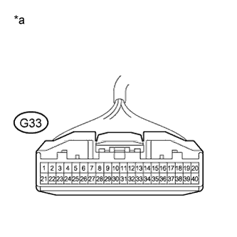
Text in Illustration *a Front view of wire harness connector
(to Main Body ECU)
Disconnect the connector of the main body ECU.
-
Text in Illustration *a Front view of wire harness connector
(to CAN No. 2 Junction Connector)
Measure the resistance according to the value(s) in the table below.
Standard Resistance Tester Connection Switch Condition Specified Condition G56-3 (CANH) - G56-14 (CANL) Engine switch off 1 MΩ or higher
NG
REPAIR OR REPLACE CAN BUS BRANCH WIRE OR CONNECTOR (CAN NO. 2 J/C - MAIN BODY ECU)
OK
-
-
CHECK FOR SHORT IN CAN BUS WIRE (MAIN BODY ECU)
-
Reconnect the connector of the CAN No. 2 junction connector.
-
Text in Illustration *1 DLC3 Measure the resistance according to the value(s) in the table below.
Standard Resistance Tester Connection Switch Condition Specified Condition G8-6 (CANH) - G8-14 (CANL) Engine switch off 54 to 69 Ω
NG
REPLACE CAN NO. 2 JUNCTION CONNECTOR
OK
REPLACE MAIN BODY ECU (PASSENGER SIDE JUNCTION BLOCK) Click here
-
-
CHECK FOR SHORT IN CAN BUS WIRE (ECM)
-
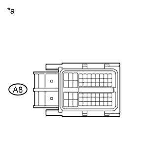
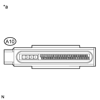
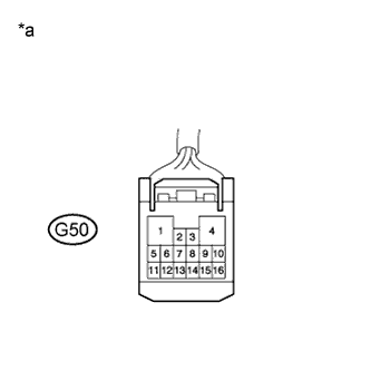
Text in Illustration *a Front view of wire harness connector
(to ECM)
Disconnect the connector of the ECM.
-
Text in Illustration *a Front view of wire harness connector
(to CAN No. 2 Junction Connector)
Measure the resistance according to the value(s) in the table below.
Standard Resistance Tester Connection Switch Condition Specified Condition G56-1 (CANH) - G56-12 (CANL) Engine switch off 1 MΩ or higher Result Result Proceed to OK (for 2AZ-FE) A OK (for 2GR-FE) B NG C
B
REPLACE ECM (for 2GR-FE) Click here
C
REPAIR OR REPLACE CAN BUS MAIN WIRE OR CONNECTOR (CAN NO. 2 J/C - ECM)
A
REPLACE ECM (for 2AZ-FE) Click here
-