CAN COMMUNICATION SYSTEM, Diagnostic DTC:U1002 (CAN MS BUS)

| DTC Code | DTC Name |
|---|---|
| U1002 (CAN MS BUS) | Lost Communication with Gateway Module (Main body ECU) |
DESCRIPTION
-
The main body ECU will store this DTC when no signals can be received from the ECUs that have been memorized as those are connected to the CAN MS bus.
-
When the main body ECU receives a response signal from the ECUs connected to the CAN MS bus, the main body ECU recognizes and memorizes that the ECU is connected to the CAN MS bus. Based on this memorized data, the main body ECU monitors for malfunctions in the ECUs connected to the CAN MS bus when communicating with those ECUs. If the main body ECU cannot receive response signals from the ECUs that have been memorized as those connected to the CAN MS bus, the main body ECU determines that a malfunction exists.
| DTC Code | DTC Detection Condition | Trouble Area |
|---|---|---|
| U1002 | Main body ECU cannot receive signals from all ECUs that have been memorized as those connected to the CAN MS bus. |
|
Tech Tips
-
*1: w/ Seat position memory
-
*2: w/ Power slide door RH
-
*3: w/ Power back door system
-
*4: w/o Power back door system
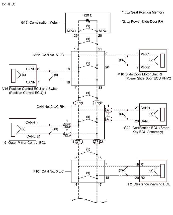
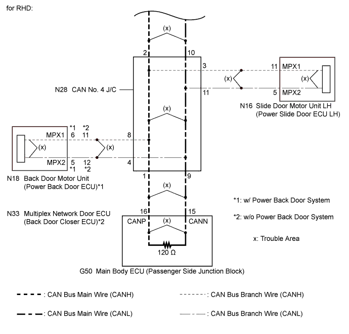
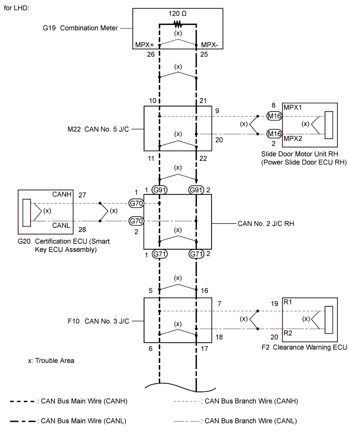
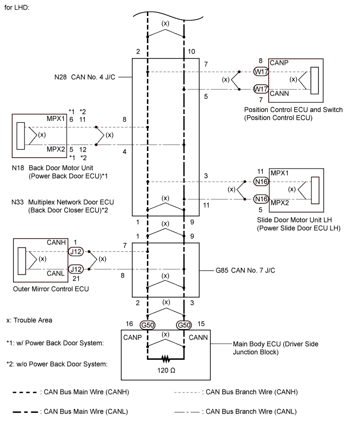
WIRING DIAGRAM
INSPECTION PROCEDURE
Note
-
Turn the engine switch off before measuring the resistances of the CAN main wire and the CAN branch wire.
-
After the engine switch is turned off, check that the key reminder warning system and light reminder warning system are not in operation.
-
Before measuring the resistance, leave the vehicle as is for at least 1 minute and do not operate the engine switch, any other switches or doors. If any doors need to be opened in order to check the connectors, open the doors and leave them open.
Tech Tips
-
Operating the engine switch, any other switches or a door triggers related ECU and sensor communication on the CAN. This communication will cause the resistance value to change.
-
Even after DTCs are cleared, if a DTC is stored again after driving the vehicle for a while, the malfunction may be occurring due to vibration of the vehicle. In such a case, wiggling the ECUs or wire harness while performing the inspection below will help determine the cause of the malfunction.
PROCEDURE
-
CHECK VEHICLE TYPE
-
Check vehicle type.
Result Result Proceed to for RHD A for LHD B
B 
CHECK CAN MS BUS WIRE Click here
A 
-
-
CHECK CAN MS BUS WIRE
-
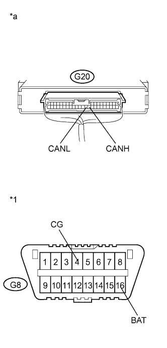
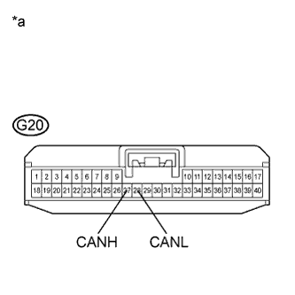
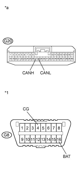
Text in Illustration *1 DLC3 *a Component with harness connected
(Certification ECU)
Turn the engine switch off.
-
Measure the resistance according to the value(s) in the table below.
Standard Resistance Tester Connection Condition Specified Condition Resistance of Malfunction G20-27 (CANH) - G20-28 (CANL) Engine switch off 54 to 69 Ω Below 54 Ω:
Short in line
70 Ω or higher:
Open in line
G20-27 (CANH) - G8-16 (BAT) Cable disconnected from negative (-) battery terminal 6 kΩ or higher Below 6 kΩ:
+B short
G20-28 (CANL) - G8-16 (BAT) Cable disconnected from negative (-) battery terminal 6 kΩ or higher Below 6 kΩ:
+B short
G20-27 (CANH) - G8-4 (CG) Engine switch off 200 Ω or higher Below 200 Ω:
Ground short
G20-28 (CANL) - G8-4 (CG) Engine switch off 200 Ω or higher Below 200 Ω:
Ground short
Result Result Proceed to OK A NG (for open in line) B NG (for short in line) C NG (for +B short or ground short) D
B
CHECK FOR OPEN IN CAN MS BUS WIRE (CAN NO. 2 J/C RH - CAN NO. 5 J/C) Click here
C
CHECK FOR SHORT IN CAN MS BUS WIRE Click here
D
CHECK FOR SHORT TO +B, GND IN CAN MS BUS WIRE (CAN NO. 2 J/C RH - CERTIFICATION ECU) Click here
A
-
-
CHECK DTC OUTPUT
-
Clear the DTCs.
-
Turn the engine switch off.
-
Turn the engine switch on (IG), recheck the DTC.
Result Result Proceed to DTC U1002 is output A Other DTC is output B
B 
GO TO CIRCUITS INDICATED BY OUTPUT DTCS
A 
REPLACE MAIN BODY ECU (PASSENGER SIDE JUNCTION BLOCK) Click here
-
-
CHECK FOR OPEN IN CAN MS BUS WIRE (CAN NO. 2 J/C RH - CAN NO. 5 J/C)
-
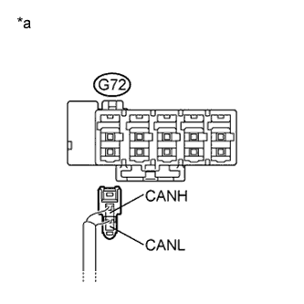
Text in Illustration *a Rear view of wire harness connector
(to CAN No. 2 Junction Connector RH)
Disconnect the CAN main wire connector (G72) from the CAN No. 2 junction connector RH (w/o earth terminal).
Note
-
Before disconnecting the connector, make a note of where it is connected.
-
Reconnect the connector to its original position.
-
-
Measure the resistance according to the value(s) in the table below.
Standard Resistance Tester Connection Switch Condition Specified Condition G72-1 (CANH) - G72-2 (CANL) Engine switch off 108 to 132 Ω
NG
CHECK FOR OPEN IN CAN MS BUS WIRE (CAN NO. 2 J/C RH - CAN NO. 5 J/C) Click here
OK
-
-
CHECK FOR OPEN IN CAN MS BUS WIRE (CAN NO. 2 J/C RH - CAN NO. 3 J/C)
-
Reconnect the CAN main wire connector (G72) to the CAN No. 2 junction connector RH (w/o earth terminal).
-
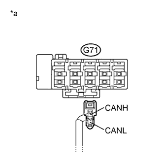
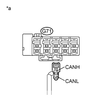
Text in Illustration *a Rear view of wire harness connector
(to CAN No. 2 Junction Connector RH)
Disconnect the CAN main wire connector (G71) from the CAN No. 2 junction connector RH (w/o earth terminal).
Note
-
Before disconnecting the connector, make a note of where it is connected.
-
Reconnect the connector to its original position.
-
-
Measure the resistance according to the value(s) in the table below.
Standard Resistance Tester Connection Switch Condition Specified Condition G71-1 (CANH) - G71-2 (CANL) Engine switch off 108 to 132 Ω
NG
CHECK FOR OPEN IN CAN MS BUS WIRE (CAN NO. 3 J/C - CAN NO. 2 J/C RH) Click here
OK
REPLACE CAN NO. 2 JUNCTION CONNECTOR RH
-
-
CHECK FOR OPEN IN CAN MS BUS WIRE (CAN NO. 2 J/C RH - CAN NO. 5 J/C)
-
Reconnect the CAN main wire connector (G72) to the CAN No. 2 junction connector RH (w/o earth terminal).
-

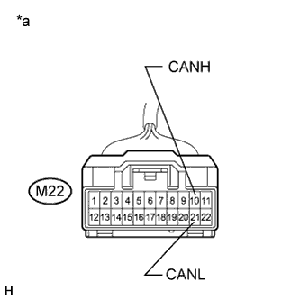
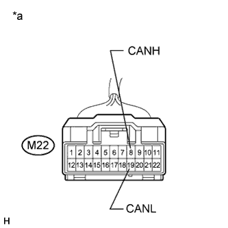
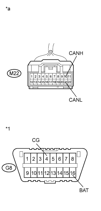
Text in Illustration *a Front view of wire harness connector
(to CAN No. 5 Junction Connector)
Disconnect the connector of the CAN No. 5 junction connector (M22).
-
Measure the resistance according to the value(s) in the table below.
Standard Resistance Tester Connection Switch Condition Specified Condition M22-11 (CANH) - M22-22 (CANL) Engine switch off 108 to 132 Ω
NG
REPAIR OR REPLACE CAN MS BUS MAIN WIRE OR CONNECTOR (CAN NO. 2 J/C RH - CAN NO. 5 J/C)
OK
-
-
CHECK FOR OPEN IN CAN MS BUS WIRE (CAN NO. 5 J/C - COMBINATION METER)
-
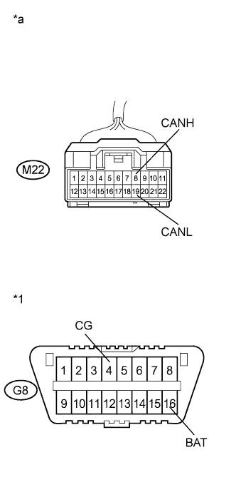
Text in Illustration *a Front view of wire harness connector
(to CAN No. 5 Junction Connector)
Measure the resistance according to the value(s) in the table below.
Standard Resistance Tester Connection Switch Condition Specified Condition M22-10 (CANH) - M22-21 (CANL) Engine switch off 108 to 132 Ω
NG
CHECK FOR OPEN IN CAN MS BUS WIRE (COMBINATION METER) Click here
OK
REPLACE CAN NO. 5 JUNCTION CONNECTOR
-
-
CHECK FOR OPEN IN CAN MS BUS WIRE (COMBINATION METER)
-
Reconnect the connector of the CAN No. 5 junction connector (M22).
-
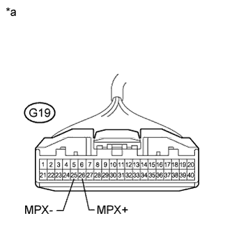
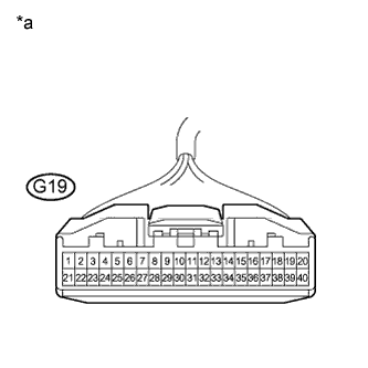
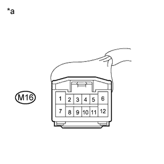
Text in Illustration *a Front view of wire harness connector
(to Combination Meter)
Disconnect the connector of the combination meter.
-
Measure the resistance according to the value(s) in the table below.
Standard Resistance Tester Connection Switch Condition Specified Condition G19-26 (MPX+) - G19-25 (MPX-) Engine switch off 108 to 132 Ω
NG
REPAIR OR REPLACE CAN MS BUS MAIN WIRE OR CONNECTOR (CAN NO. 5 J/C - COMBINATION METER)
OK
REPLACE COMBINATION METER Click here
-
-
CHECK FOR OPEN IN CAN MS BUS WIRE (CAN NO. 3 J/C - CAN NO. 2 J/C RH)
-
Reconnect the CAN main wire connector (G71) to the CAN No. 2 junction connector RH (w/o earth terminal).
-
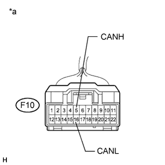
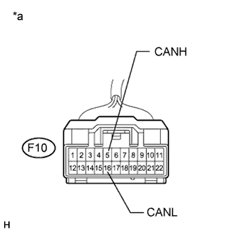
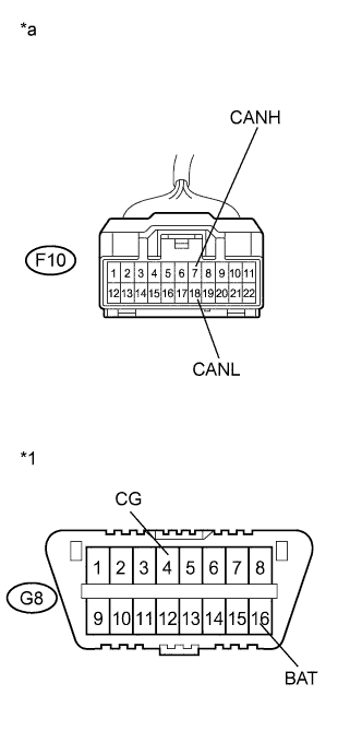
Text in Illustration *a Front view of wire harness connector
(to CAN No. 3 Junction Connector)
Disconnect the connector of the CAN No. 3 junction connector (F10).
-
Measure the resistance according to the value(s) in the table below.
Standard Resistance Tester Connection Switch Condition Specified Condition F10-5 (CANH) - F10-16 (CANL) Engine switch off 108 to 132 Ω
NG
REPAIR OR REPLACE CAN MS BUS MAIN WIRE OR CONNECTOR (CAN NO. 2 J/C RH - CAN NO. 3 J/C)
OK
-
-
CHECK FOR OPEN IN CAN MS BUS WIRE (CAN NO. 3 J/C - CAN NO. 4 J/C)
-

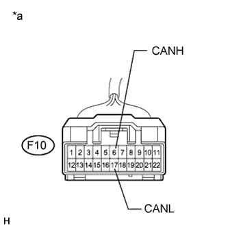
Text in Illustration *a Front view of wire harness connector
(to CAN No. 3 Junction Connector)
Measure the resistance according to the value(s) in the table below.
Standard Resistance Tester Connection Switch Condition Specified Condition F10-6 (CANH) - F10-17 (CANL) Engine switch off 108 to 132 Ω
NG
CHECK FOR OPEN IN CAN MS BUS WIRE (CAN NO. 4 J/C - CAN NO. 3 J/C) Click here
OK
REPLACE CAN NO. 3 JUNCTION CONNECTOR
-
-
CHECK FOR OPEN IN CAN MS BUS WIRE (CAN NO. 4 J/C - CAN NO. 3 J/C)
-
Reconnect the connector of the CAN No. 3 junction connector (F10).
-
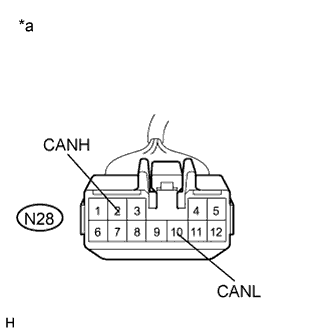
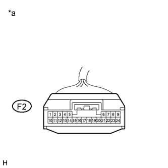
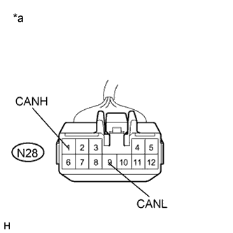
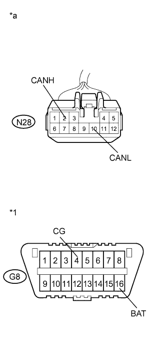
Text in Illustration *a Front view of wire harness connector
(to CAN No. 4 Junction Connector)
Disconnect the connector of the CAN No. 4 junction connector (N28).
-
Measure the resistance according to the value(s) in the table below.
Standard Resistance Tester Connection Switch Condition Specified Condition N28-2 (CANH) - N28-10 (CANL) Engine switch off 108 to 132 Ω
NG
REPAIR OR REPLACE CAN MS BUS MAIN WIRE OR CONNECTOR (CAN NO. 3 J/C - CAN NO. 4 J/C)
OK
-
-
CHECK FOR OPEN IN CAN MS BUS WIRE (CAN NO. 4 J/C - MAIN BODY ECU)
-

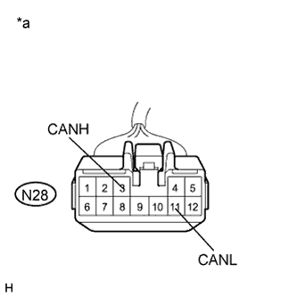
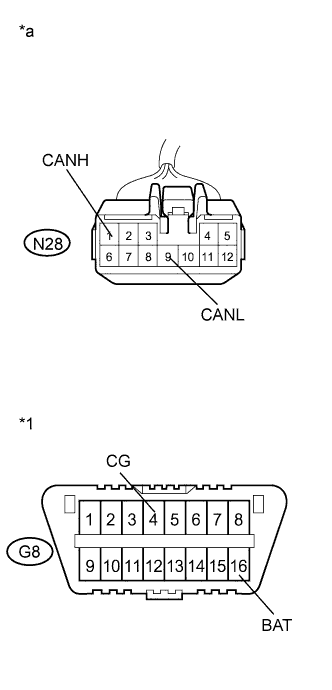
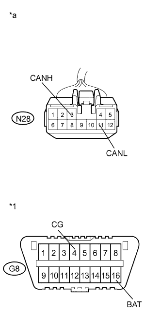
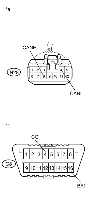
Text in Illustration *a Front view of wire harness connector
(to CAN No. 4 Junction Connector)
Measure the resistance according to the value(s) in the table below.
Standard Resistance Tester Connection Switch Condition Specified Condition N28-1 (CANH) - N28-9 (CANL) Engine switch off 108 to 132 Ω
NG
CHECK FOR OPEN IN CAN MS BUS WIRE (MAIN BODY ECU) Click here
OK
REPLACE CAN NO. 4 JUNCTION CONNECTOR
-
-
CHECK FOR OPEN IN CAN MS BUS WIRE (MAIN BODY ECU)
-
Reconnect the connector of the CAN No. 4 junction connector (N28).
-
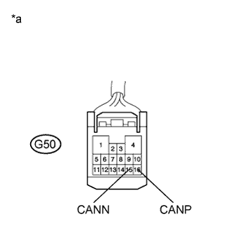
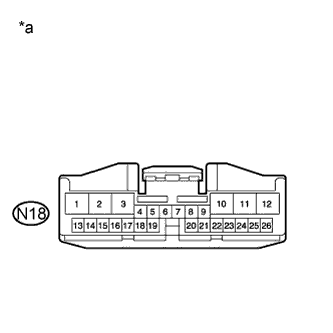
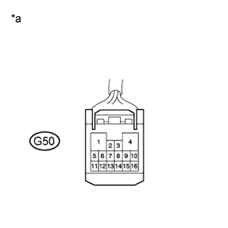
Text in Illustration *a Front view of wire harness connector
(to Main Body ECU)
Disconnect the connector of the main body ECU.
-
Measure the resistance according to the value(s) in the table below.
Standard Resistance Tester Connection Switch Condition Specified Condition G50-16 (CANP) - G50-15 (CANN) Engine switch off 108 to 132 Ω
NG
REPAIR OR REPLACE CAN MS BUS MAIN WIRE OR CONNECTOR (CAN NO. 4 J/C - MAIN BODY ECU)
OK
REPLACE MAIN BODY ECU (PASSENGER SIDE JUNCTION BLOCK) Click here
-
-
CHECK FOR SHORT IN CAN MS BUS WIRE
-
Text in Illustration *a Front view of wire harness connector
(to Certification ECU)
Disconnect the connector of the certification ECU.
-
Measure the resistance according to the value(s) in the table below.
Standard Resistance Tester Connection Switch Condition Specified Condition G20-27 (CANH) - G20-28 (CANL) Engine switch off 54 to 69 Ω
NG
CHECK FOR SHORT IN CAN MS BUS WIRE (CAN NO. 2 J/C RH - CERTIFICATION ECU) Click here
OK
REPLACE CERTIFICATION ECU (SMART KEY ECU ASSEMBLY)
-
-
CHECK FOR SHORT IN CAN MS BUS WIRE (CAN NO. 2 J/C RH - CERTIFICATION ECU)
-
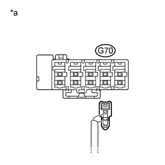
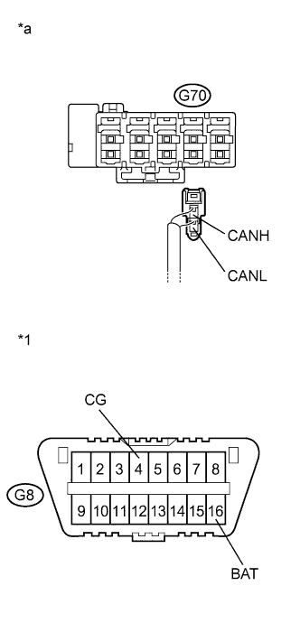
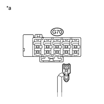
Text in Illustration *a Rear view of wire harness connector
(to CAN No. 2 Junction Connector RH)
Disconnect the CAN branch wire connector (G70) from the CAN No. 2 junction connector RH (w/o earth terminal).
Note
-
Before disconnecting the connector, make a note of where it is connected.
-
Reconnect the connector to its original position.
-
-
Text in Illustration *a Front view of wire harness connector
(to Certification ECU)
Measure the resistance according to the value(s) in the table below.
Standard Resistance Tester Connection Switch Condition Specified Condition G20-27 (CANH) - G20-28 (CANL) Engine switch off 1 MΩ or higher
NG
REPAIR OR REPLACE CAN MS BUS BRANCH WIRE OR CONNECTOR (CAN NO. 2 J/C RH - CERTIFICATION ECU)
OK
-
-
CHECK FOR SHORT IN CAN MS BUS WIRE (CAN NO. 2 J/C RH - CAN NO. 5 J/C)
-
Reconnect the CAN branch wire connector (G70) to the CAN No. 2 junction connector RH (w/o earth terminal).
-
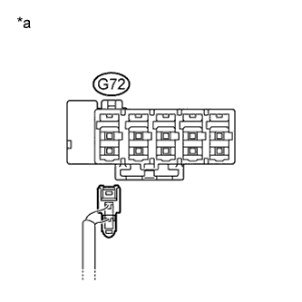
Text in Illustration *a Rear view of wire harness connector
(to CAN No. 2 Junction Connector RH)
Disconnect the CAN main wire connector (G72) from the CAN No. 2 junction connector RH (w/o earth terminal).
Note
-
Before disconnecting the connector, make a note of where it is connected.
-
Reconnect the connector to its original position.
-
-
Text in Illustration *a Front view of wire harness connector
(to Certification ECU)
Measure the resistance according to the value(s) in the table below.
Standard Resistance Tester Connection Switch Condition Specified Condition G20-27 (CANH) - G20-28 (CANL) Engine switch off 108 to 132 Ω Result Result Proceed to The resistance is still below 54 Ω when the specified connectors are disconnected. (There is a short in the bus wires.) A The resistance becomes normal (between 108 to 132 Ω) when a connector is disconnected. (There is a short in the disconnected bus wires.) B
B
CHECK FOR SHORT IN CAN MS BUS WIRE (CAN NO. 5 J/C - CAN NO. 2 J/C RH) Click here
A
-
-
CHECK FOR SHORT IN CAN MS BUS WIRE (CAN NO. 2 J/C RH - CAN NO. 3 J/C)
-
Reconnect the CAN main wire connector (G72) to the CAN No. 2 junction connector RH (w/o earth terminal).
-
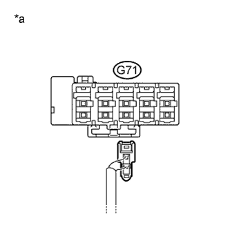
Text in Illustration *a Rear view of wire harness connector
(to CAN No. 2 Junction Connector RH)
Disconnect the CAN main wire connector (G71) from the CAN No. 2 junction connector RH (w/o earth terminal).
Note
-
Before disconnecting the connector, make a note of where it is connected.
-
Reconnect the connector to its original position.
-
-
Text in Illustration *a Front view of wire harness connector
(to Certification ECU)
Measure the resistance according to the value(s) in the table below.
Standard Resistance Tester Connection Switch Condition Specified Condition G20-27 (CANH) - G20-28 (CANL) Engine switch off 108 to 132 Ω Result Result Proceed to The resistance is still below 54 Ω when all the specified connectors are disconnected. (There is a short in the bus wires.) A The resistance becomes normal (between 108 to 132 Ω) when a connector is disconnected. (There is a short in the disconnected bus wires.) B
B
CHECK FOR SHORT IN CAN MS BUS WIRE (CAN NO. 3 J/C - CAN NO. 2 J/C RH) Click here
A
-
-
CHECK FOR SHORT IN CAN MS BUS WIRE (CAN NO. 2 J/C RH)
-
Text in Illustration *a Front view of wire harness connector
(to Certification ECU)
Connect the probes of an ohmmeter to terminals CANH and CANL of the DLC3.
-
While observing the resistance value shown on the tester, disconnect connector (G73) from the CAN No. 2 junction connector RH and check if the resistance becomes normal (between 54 and 69 Ω).
Tech Tips
Disconnect the branch wire connector other than those of the certification ECU.
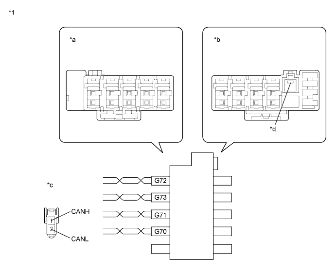
for CAN Junction Connector B Side Terminal No. (Symbol) Wiring Color Connected to G70-1 (CANH) SB Certification ECU (Smart key ECU assembly) G70-2 (CANL) W G71-1 (CANH) B CAN No. 3 junction connector G71-2 (CANL) W G72-1 (CANH) B CAN No. 5 junction connector G72-2 (CANL) W G73-1 (CANH) P Outer mirror control ECU G73-2 (CANL) W Text in Illustration *1 CAN No. 2 Junction Connector RH - - *a Junction Connector B Side *b Junction Connector A Side *c Front view of wire harness connector
(to CAN No. 2 Junction Connector RH)
*d Earth Terminal Result Result Proceed to The resistance is still below 54 Ω when the specified connector is disconnected. (There is no short in the branch wires.) A The resistance becomes normal (between 54 and 69 Ω) when the connector is disconnected. (There is a short in one or more of the branch wires.) B -
When there is a short in one or more of the branch wires:
-
Reconnect all of the connectors to the CAN junction connector, except for the one that was disconnected last (the short-circuited bus wire). Check that the resistance shown on the tester becomes normal (between 54 and 69 Ω) to confirm that there is a short in only one branch wire.
Tech Tips
-
The shape of connectors connected to the CAN junction connector which has an earth terminal is the same. The connectors connected to the CAN junction connector can be distinguished by the colors of the bus wire and the connecting side of the junction connector.
-
Reconnecting the connectors to non-specified positions on the CAN junction connector does not affect system operation. However, it is preferred to reconnect the connectors to their specified positions to avoid negative effects on the wiring such as tension on the wiring harnesses, and to make future maintenance easier.
-
-
B
CHECK FOR SHORT IN CAN MS BUS WIRE Click here
A
REPLACE CAN NO. 2 JUNCTION CONNECTOR RH
-
-
CHECK FOR SHORT IN CAN MS BUS WIRE
-
Reconnect the CAN main wire connector (G71) to the CAN No. 2 junction connector RH (w/o earth terminal).
-
Reconnect the CAN main wire connector (G72) to the CAN No. 2 junction connector RH (w/o earth terminal).
-
Reconnect the connector for the short-circuited branch wire to the CAN junction connector (the connector that caused the bus wire resistance to become normal (between 54 and 69 Ω) when it was disconnected).
-
Disconnect the connector that includes terminals CANH and CANL from the ECU to which the short-circuited branch wire is connected.
-
Text in Illustration *a Front view of wire harness connector
(to Certification ECU)
Measure the resistance according to the value(s) in the table below.
Connect the probes of an ohmmeter to terminals CANH and CANL of the DLC3.
Standard Resistance Tester Connection Switch Condition Specified Condition G20-27 (CANH) - G20-28 (CANL) Engine switch off 54 to 69 Ω Tech Tips
If the resistance becomes normal (between 54 and 69 Ω) when the connector is disconnected from the ECU, there may be a short in the ECU.
NG
REPAIR OR REPLACE CORRESPONDING ECU BRANCH WIRE OR CONNECTOR
OK
REPLACE CORRESPONDING ECU
-
-
CHECK FOR SHORT IN CAN MS BUS WIRE (CAN NO. 5 J/C - CAN NO. 2 J/C RH)
-
Text in Illustration *a Front view of wire harness connector
(to CAN No. 5 Junction Connector)
Disconnect the connector of the CAN No. 5 junction connector (M22).
-
Measure the resistance according to the value(s) in the table below.
Standard Resistance Tester Connection Switch Condition Specified Condition M22-11 (CANH) - M22-22 (CANL) Engine switch off 1 MΩ or higher
NG
REPAIR OR REPLACE CAN MS BUS MAIN WIRE OR CONNECTOR (CAN NO. 2 J/C RH - CAN NO. 5 J/C)
OK
-
-
CHECK FOR SHORT IN CAN MS BUS WIRE (CAN NO. 5 J/C - COMBINATION METER)
-
Text in Illustration *a Front view of wire harness connector
(to CAN No. 5 Junction Connector)
Measure the resistance according to the value(s) in the table below.
Standard Resistance Tester Connection Switch Condition Specified Condition M22-10 (CANH) - M22-21 (CANL) Engine switch off 108 to 132 Ω
NG
CHECK FOR SHORT IN CAN MS BUS WIRE (COMBINATION METER) Click here
OK
-
-
CHECK FOR SHORT IN CAN MS BUS WIRE (CAN NO. 5 J/C - POWER SLIDE DOOR ECU RH)
-
Text in Illustration *a Front view of wire harness connector
(to Power Slide Door ECU RH)
Disconnect the connector of the power slide door ECU RH.
-

Text in Illustration *a Front view of wire harness connector
(to CAN No. 5 Junction Connector)
Measure the resistance according to the value(s) in the table below.
Standard Resistance Tester Connection Switch Condition Specified Condition M22-9 (CANH) - M22-20 (CANL) Engine switch off 1 MΩ or higher
NG
REPAIR OR REPLACE CAN MS BUS BRANCH WIRE OR CONNECTOR (CAN NO. 5 J/C - POWER SLIDE DOOR ECU RH)
OK
-
-
CHECK FOR SHORT IN CAN MS BUS WIRE (POWER SLIDE DOOR ECU RH)
-
Reconnect the CAN main wire connector (G72) to the CAN No. 2 junction connector RH (w/o earth terminal).
-
Reconnect the connector of the CAN No. 5 junction connector (M22).
-
Text in Illustration *a Front view of wire harness connector
(to Certification ECU)
Measure the resistance according to the value(s) in the table below.
Connect the probes of an ohmmeter to terminals CANH and CANL of the DLC3.
Standard Resistance Tester Connection Switch Condition Specified Condition G20-27 (CANH) - G20-28 (CANL) Engine switch off 54 to 69 Ω
NG
CHECK FOR SHORT IN CAN MS BUS WIRE (CAN NO. 5 J/C - POSITION CONTROL ECU) Click here
OK
REPLACE SLIDE DOOR MOTOR UNIT RH (POWER SLIDE DOOR ECU RH) Click here
-
-
CHECK FOR SHORT IN CAN MS BUS WIRE (CAN NO. 5 J/C - POSITION CONTROL ECU)
-
Disconnect the connector of the CAN No. 5 junction connector (M22).
-

Text in Illustration *a Front view of wire harness connector
(to Position Control ECU)
Disconnect the connector of the position control ECU.
-
Text in Illustration *a Front view of wire harness connector
(to CAN No. 5 Junction Connector)
Measure the resistance according to the value(s) in the table below.
Standard Resistance Tester Connection Switch Condition Specified Condition M22-8 (CANH) - M22-19 (CANL) Engine switch off 1 MΩ or higher
NG
REPAIR OR REPLACE CAN MS BUS BRANCH WIRE OR CONNECTOR (CAN NO. 5 J/C - POSITION CONTROL ECU)
OK
-
-
CHECK FOR SHORT IN CAN MS BUS WIRE (POSITION CONTROL ECU)
-
Reconnect the connector of the CAN No. 5 junction connector (M22).
-
Text in Illustration *a Front view of wire harness connector
(to Certification ECU)
Measure the resistance according to the value(s) in the table below.
Standard Resistance Tester Connection Switch Condition Specified Condition G20-27 (CANH) - G20-28 (CANL) Engine switch off 54 to 69 Ω
NG
REPLACE CAN NO. 5 JUNCTION CONNECTOR
OK
REPLACE POSITION CONTROL ECU AND SWITCH (POSITION CONTROL ECU) Click here
-
-
CHECK FOR SHORT IN CAN MS BUS WIRE (COMBINATION METER)
-
Text in Illustration *a Front view of wire harness connector
(to Combination Meter)
Disconnect the connector of the combination meter.
-
Text in Illustration *a Front view of wire harness connector
(to CAN No. 5 Junction Connector)
Measure the resistance according to the value(s) in the table below.
Standard Resistance Tester Connection Switch Condition Specified Condition M22-10 (CANH) - M22-21 (CANL) Engine switch off 1 MΩ or higher
NG
REPAIR OR REPLACE CAN MS BUS MAIN WIRE OR CONNECTOR (CAN NO. 5 J/C - COMBINATION METER)
OK
REPLACE COMBINATION METER Click here
-
-
CHECK FOR SHORT IN CAN MS BUS WIRE (CAN NO. 3 J/C - CAN NO. 2 J/C RH)
-
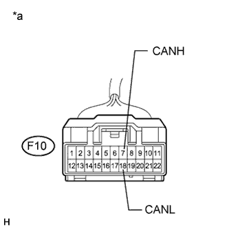
Text in Illustration *a Front view of wire harness connector
(to CAN No. 3 Junction Connector)
Disconnect the connector of the CAN No. 3 junction connector (F10).
-
Measure the resistance according to the value(s) in the table below.
Standard Resistance Tester Connection Switch Condition Specified Condition F10-5 (CANH) - F10-16 (CANL) Engine switch off 1 MΩ or higher
NG
REPAIR OR REPLACE CAN MS BUS MAIN WIRE OR CONNECTOR (CAN NO. 2 J/C RH - CAN NO. 3 J/C)
OK
-
-
CHECK FOR SHORT IN CAN MS BUS WIRE (CAN NO. 3 J/C - CAN NO. 4 J/C)
-
Text in Illustration *a Front view of wire harness connector
(to CAN No. 3 Junction Connector)
Measure the resistance according to the value(s) in the table below.
Standard Resistance Tester Connection Switch Condition Specified Condition F10-6 (CANH) - F10-17 (CANL) Engine switch off 108 to 132 Ω
NG
CHECK FOR SHORT IN CAN MS BUS WIRE (CAN NO. 4 J/C - CAN NO. 3 J/C) Click here
OK
-
-
CHECK FOR SHORT IN CAN MS BUS WIRE (CAN NO. 3 J/C - CLEARANCE WARNING ECU)
-
Text in Illustration *a Front view of wire harness connector
(to Clearance Warning ECU)
Disconnect the connector of the clearance warning ECU.
-
Text in Illustration *a Front view of wire harness connector
(to CAN No. 3 Junction Connector)
Measure the resistance according to the value(s) in the table below.
Standard Resistance Tester Connection Switch Condition Specified Condition F10-7 (CANH) - F10-18 (CANL) Engine switch off 1 MΩ or higher
NG
REPAIR OR REPLACE CAN MS BUS BRANCH WIRE OR CONNECTOR (CAN NO. 3 J/C - CLEARANCE WARNING ECU)
OK
-
-
CHECK FOR SHORT IN CAN MS BUS WIRE (CLEARANCE WARNING ECU)
-
Reconnect the connector of the CAN No. 3 junction connector (F10).
-
Text in Illustration *a Front view of wire harness connector
(to Certification ECU)
Measure the resistance according to the value(s) in the table below.
Standard Resistance Tester Connection Switch Condition Specified Condition G20-27 (CANH) - G20-28 (CANL) Engine switch off 54 to 69 Ω
NG
REPLACE CAN NO. 3 JUNCTION CONNECTOR
OK
REPLACE CLEARANCE WARNING ECU Click here
-
-
CHECK FOR SHORT IN CAN MS BUS WIRE (CAN NO. 4 J/C - CAN NO. 3 J/C)
-

Text in Illustration *a Front view of wire harness connector
(to CAN No. 4 Junction Connector)
Disconnect the connector of the CAN No. 4 junction connector (N28).
-
Measure the resistance according to the value(s) in the table below.
Standard Resistance Tester Connection Switch Condition Specified Condition N28-2 (CANH) - N28-10 (CANL) Engine switch off 1 MΩ or higher
NG
REPAIR OR REPLACE CAN MS BUS MAIN WIRE OR CONNECTOR (CAN NO. 3 J/C - CAN NO. 4 J/C)
OK
-
-
CHECK FOR SHORT IN CAN MS BUS WIRE (CAN NO. 4 J/C - MAIN BODY ECU)
-
Text in Illustration *a Front view of wire harness connector
(to CAN No. 4 Junction Connector)
Measure the resistance according to the value(s) in the table below.
Standard Resistance Tester Connection Switch Condition Specified Condition N28-1 (CANH) - N28-9 (CANL) Engine switch off 108 to 132 Ω
NG
CHECK FOR SHORT IN CAN MS BUS WIRE (MAIN BODY ECU) Click here
OK
-
-
CHECK FOR SHORT IN CAN MS BUS WIRE (CAN NO. 4 J/C - POWER SLIDE DOOR ECU LH)
-

Text in Illustration *a Front view of wire harness connector
(to Power Slide Door ECU LH)
Disconnect the connector of the power slide door ECU LH.
-
Text in Illustration *a Front view of wire harness connector
(to CAN No. 4 Junction Connector)
Measure the resistance according to the value(s) in the table below.
Standard Resistance Tester Connection Switch Condition Specified Condition N28-3 (CANH) - N28-11 (CANL) Engine switch off 1 MΩ or higher
NG
REPAIR OR REPLACE CAN MS BUS BRANCH WIRE OR CONNECTOR (CAN NO. 4 J/C - POWER SLIDE DOOR ECU LH)
OK
-
-
CHECK FOR SHORT IN CAN MS BUS WIRE (POWER SLIDE DOOR ECU LH)
-
Reconnect the connector of the CAN No. 3 junction connector (F10).
-
Reconnect the connector of the CAN No. 4 junction connector (N28).
-
Text in Illustration *a Front view of wire harness connector
(to Certification ECU)
Measure the resistance according to the value(s) in the table below.
Standard Resistance Tester Connection Switch Condition Specified Condition G20-27 (CANH) - G20-28 (CANL) Engine switch off 54 to 69 Ω Result Result Proceed to OK A NG (w/ Power back door system) B NG (w/o Power back door system) C
B
CHECK FOR SHORT IN CAN MS BUS WIRE (CAN NO. 4 J/C - POWER BACK DOOR ECU) Click here
C
REPLACE CAN NO. 4 JUNCTION CONNECTOR
A
REPLACE SLIDE DOOR MOTOR UNIT LH (POWER SLIDE DOOR ECU LH) Click here
-
-
CHECK FOR SHORT IN CAN MS BUS WIRE (CAN NO. 4 J/C - POWER BACK DOOR ECU)
-
Disconnect the connector of the CAN No. 4 junction connector (N28).
-
Text in Illustration *a Front view of wire harness connector
(to Power Back Door ECU)
Disconnect the connector of the power back door ECU.
-

Text in Illustration *a Front view of wire harness connector
(to CAN No. 4 Junction Connector)
Measure the resistance according to the value(s) in the table below.
Standard Resistance Tester Connection Switch Condition Specified Condition N28-8 (CANH) - N28-4 (CANL) Engine switch off 1 MΩ or higher
NG
REPAIR OR REPLACE CAN MS BUS BRANCH WIRE OR CONNECTOR (CAN NO. 4 J/C - POWER BACK DOOR ECU)
OK
-
-
CHECK FOR SHORT IN CAN MS BUS WIRE (POWER BACK DOOR ECU)
-
Reconnect the connector of the CAN No. 4 junction connector (N28).
-
Text in Illustration *a Front view of wire harness connector
(to Certification ECU)
Measure the resistance according to the value(s) in the table below.
Standard Resistance Tester Connection Switch Condition Specified Condition G20-27 (CANH) - G20-28 (CANL) Engine switch off 54 to 69 Ω
NG
REPLACE CAN NO. 4 JUNCTION CONNECTOR
OK
REPLACE BACK DOOR MOTOR UNIT (POWER BACK DOOR ECU) Click here
-
-
CHECK FOR SHORT IN CAN MS BUS WIRE (MAIN BODY ECU)
-
Text in Illustration *a Front view of wire harness connector
(to Main Body ECU)
Disconnect the connector of the main body ECU.
-
Text in Illustration *a Front view of wire harness connector
(to CAN No. 4 Junction Connector)
Measure the resistance according to the value(s) in the table below.
Standard Resistance Tester Connection Switch Condition Specified Condition N28-1 (CANH) - N28-9 (CANL) Engine switch off 1 MΩ or higher
NG
REPAIR OR REPLACE CAN MS BUS MAIN WIRE OR CONNECTOR (CAN NO. 4 J/C - MAIN BODY ECU)
OK
REPLACE MAIN BODY ECU (PASSENGER SIDE JUNCTION BLOCK) Click here
-
-
CHECK FOR SHORT TO +B, GND IN CAN MS BUS WIRE (CAN NO. 2 J/C RH - CERTIFICATION ECU)
-
Text in Illustration *1 DLC3 *a Rear view of wire harness connector
(to CAN No. 2 Junction Connector RH)
Disconnect the CAN branch wire connector (G70) from the CAN No. 2 junction connector RH (w/o earth terminal).
Note
-
Before disconnecting the connector, make a note of where it is connected.
-
Reconnect the connector to its original position.
-
-
Measure the resistance according to the value(s) in the table below.
Standard Resistance Tester Connection Condition Specified Condition G70-1 (CANH) - G8-16 (BAT) Cable disconnected from negative (-) battery terminal 6 kΩ or higher G70-2 (CANL) - G8-16 (BAT) Cable disconnected from negative (-) battery terminal 6 kΩ or higher G70-1 (CANH) - G8-4 (CG) Engine switch off 200 Ω or higher G70-2 (CANL) - G8-4 (CG) Engine switch off 200 Ω or higher Result Result Proceed to The resistance between terminals 6 (CANH) and 16 (BAT), or the resistance between 14 (CANL) and 16 (BAT) is still below 6 kΩ when all the specified connectors are disconnected from the CAN junction connector. (There is a short to +B in the bus wires.) A The resistance between terminals 6 (CANH) and 4 (CG), or the resistance between 14 (CANL) and 4 (CG) is still below 200 Ω when all the specified connectors are disconnected from the CAN junction connector. (There is a short to GND in the bus wires.) The resistance between terminals 6 (CANH) and 16 (BAT), or the resistance between 14 (CANL) and 16 (BAT) becomes normal (6 kΩ or higher) when a connector is disconnected from the CAN junction connector. (There is a short to +B in the disconnected bus wires.) B The resistance between terminals 6 (CANH) and 4 (CG), or the resistance between 14 (CANL) and 4 (CG)becomes normal (200 Ω or higher) when a connector is disconnected from the CAN junction connector. (There is a short to GND in the disconnected bus wires.)
B
CHECK FOR SHORT TO +B, GND IN CAN MS BUS WIRE (CAN NO. 2 J/C RH - CAN NO. 5 J/C) Click here
A
-
-
CHECK FOR SHORT TO +B, GND IN CAN MS BUS WIRE (CERTIFICATION ECU)
-
Text in Illustration *1 DLC3 *a Front view of wire harness connector
(to Certification ECU)
Disconnect the connector of the certification ECU.
-
Measure the resistance according to the value(s) in the table below.
Standard Resistance Tester Connection Condition Specified Condition G20-27 (CANH) - G8-16 (BAT) Cable disconnected from negative (-) battery terminal 6 kΩ or higher G20-28 (CANL) - G8-16 (BAT) Cable disconnected from negative (-) battery terminal 6 kΩ or higher G20-27 (CANH) - G8-4 (CG) Engine switch off 200 Ω or higher G20-28 (CANL) - G8-4 (CG) Engine switch off 200 Ω or higher
NG
REPAIR OR REPLACE CAN MS BUS BRANCH WIRE OR CONNECTOR (CAN NO. 2 J/C RH - CERTIFICATION ECU)
OK
REPLACE CERTIFICATION ECU (SMART KEY ECU ASSEMBLY)
-
-
CHECK FOR SHORT TO +B, GND IN CAN MS BUS WIRE (CAN NO. 2 J/C RH - CAN NO. 5 J/C)
-
Reconnect the CAN branch wire connector (G70) to the CAN No. 2 junction connector RH (w/o earth terminal).
-
Disconnect the connector of the certification ECU.
-
Text in Illustration *a Rear view of wire harness connector
(to CAN No. 2 Junction Connector RH)
Disconnect the CAN main wire connector (G72) from the CAN No. 2 junction connector RH (w/o earth terminal).
-
Text in Illustration *1 DLC3 *a Front view of wire harness connector
(to Certification ECU)
Measure the resistance according to the value(s) in the table below.
Standard Resistance Tester Connection Condition Specified Condition G20-27 (CANH) - G8-16 (BAT) Cable disconnected from negative (-) battery terminal 6 kΩ or higher G20-28 (CANL) - G8-16 (BAT) Cable disconnected from negative (-) battery terminal 6 kΩ or higher G20-27 (CANH) - G8-4 (CG) Engine switch off 200 Ω or higher G20-28 (CANL) - G8-4 (CG) Engine switch off 200 Ω or higher Result Result Proceed to The resistance between terminals 6 (CANH) and 16 (BAT), or the resistance between 14 (CANL) and 16 (BAT) is still below 6 kΩ when all the specified connectors are disconnected from the CAN junction connector. (There is a short to +B in the bus wires.) A The resistance between terminals 6 (CANH) and 4 (CG), or the resistance between 14 (CANL) and 4 (CG) is still below 200 Ω when all the specified connectors are disconnected from the CAN junction connector. (There is a short to GND in the bus wires.) The resistance between terminals 6 (CANH) and 16 (BAT), or the resistance between 14 (CANL) and 16 (BAT) becomes normal (6 kΩ or higher) when a connector is disconnected from the CAN junction connector. (There is a short to +B in the disconnected bus wires.) B The resistance between terminals 6 (CANH) and 4 (CG), or the resistance between 14 (CANL) and 4 (CG) becomes normal (200 Ω or higher) when a connector is disconnected from the CAN junction connector. (There is a short to GND in the disconnected bus wires.)
B
CHECK FOR SHORT TO +B, GND IN CAN MS BUS WIRE (CAN NO. 5 J/C - CAN NO. 2 J/C RH) Click here
A
-
-
CHECK FOR SHORT TO +B, GND IN CAN MS BUS WIRE (CAN NO. 2 J/C RH - CAN NO. 3 J/C)
-
Reconnect the CAN main wire connector (G72) to the CAN No. 2 junction connector RH (w/o earth terminal).
-
Text in Illustration *a Rear view of wire harness connector
(to CAN No. 2 Junction Connector RH)
Disconnect the CAN main wire connector (G71) from the CAN No. 2 junction connector RH (w/o earth terminal).
Note
-
Before disconnecting the connector, make a note of where it is connected.
-
Reconnect the connector to its original position.
-
-
Text in Illustration *1 DLC3 *a Front view of wire harness connector
(to Certification ECU)
Measure the resistance according to the value(s) in the table below.
Standard Resistance Tester Connection Condition Specified Condition G20-27 (CANH) - G8-16 (BAT) Cable disconnected from negative (-) battery terminal 6 kΩ or higher G20-28 (CANL) - G8-16 (BAT) Cable disconnected from negative (-) battery terminal 6 kΩ or higher G20-27 (CANH) - G8-4 (CG) Engine switch off 200 Ω or higher G20-28 (CANL) - G8-4 (CG) Engine switch off 200 Ω or higher Result Result Proceed to The resistance between terminals 6 (CANH) and 16 (BAT), or the resistance between 14 (CANL) and 16 (BAT) is still below 6 kΩ when all the specified connectors are disconnected from the CAN junction connector. (There is a short to +B in the bus wires.) A The resistance between terminals 6 (CANH) and 4 (CG), or the resistance between 14 (CANL) and 4 (CG) is still below 200 Ω when all the specified connectors are disconnected from the CAN junction connector. (There is a short to GND in the bus wires.) The resistance between terminals 6 (CANH) and 16 (BAT), or the resistance between 14 (CANL) and 16 (BAT) becomes normal (6 kΩ or higher) when a connector is disconnected from the CAN junction connector. (There is a short to +B in the disconnected bus wires.) B The resistance between terminals 6 (CANH) and 4 (CG), or the resistance between 14 (CANL) and 4 (CG) becomes normal (200 Ω or higher) when a connector is disconnected from the CAN junction connector. (There is a short to GND in the disconnected bus wires.)
B
CHECK FOR SHORT TO +B, GND IN CAN MS BUS WIRE (CAN NO. 3 J/C - CAN NO. 2 J/C RH) Click here
A
-
-
CHECK FOR SHORT TO +B, GND IN CAN MS BUS WIRE (CAN NO. 2 J/C RH)
-
Text in Illustration *1 DLC3 *a Front view of wire harness connector
(to Certification ECU)
Connect the probes of an ohmmeter to terminals CANH and CANL of the DLC3.
-
While observing the resistance value shown on the tester, disconnect connector (G73) from the CAN No. 2 junction connector RH until the resistance becomes normal (6 kΩ or higher (for +B short) or 200 Ω or higher (for ground short)).
Tech Tips
Disconnect the branch wire connector other than those of the certification ECU.
for CAN Junction Connector B Side Terminal No. (Symbol) Wiring Color Connected to G70-1 (CANH) SB Certification ECU (Smart key ECU assembly) G70-2 (CANL) W G71-1 (CANH) B CAN No. 3 junction connector G71-2 (CANL) W G72-1 (CANH) B CAN No. 5 junction connector G72-2 (CANL) W G73-1 (CANH) P Outer mirror control ECU G73-2 (CANL) W Text in Illustration *1 CAN No. 2 Junction Connector RH - - *a Junction Connector B Side *b Junction Connector A Side *c Front view of wire harness connector
(to CAN No. 2 Junction Connector RH)
*d Earth Terminal Note
Do not reconnect the disconnected connectors until this inspection is complete because there may be a short to +B or GND in 2 or more branch wires.
Result Result Proceed to The resistance between terminals 6 (CANH) and 16 (BAT), or the resistance between 14 (CANL) and 16 (BAT) is still below 6 kΩ when all the specified connectors are disconnected from the CAN junction connector. (There is no short to +B in the branch wires.) A The resistance between terminals 6 (CANH) and 4 (CG), or the resistance between 14 (CANL) and 4 (CG) is still below 200 Ω when all the specified connectors are disconnected from the CAN junction connector. (There is no short to GND in the branch wires.) The resistance between terminals 6 (CANH) and 16 (BAT), or the resistance between 14 (CANL) and 16 (BAT) becomes normal (6 kΩ or higher) when a connector is disconnected from the CAN junction connector. (There is a short to +B in one of the areas related to one or more of the disconnected branch wires.) B The resistance between terminals 6 (CANH) and 4 (CG), or the resistance between 14 (CANL) and 4 (CG) becomes normal (200 Ω or higher) when a connector is disconnected from the CAN junction connector. (There is a short to GND in one of the areas related to one or more of the disconnected branch wires.) -
When there is a short to +B or GND in one or more of the branch wires:
-
Reconnect all of the connectors to the CAN junction connector, except for the one that was disconnected last (the bus wire that is shorted to +B or GND). Check that the resistance shown on the tester becomes normal (6 kΩ or higher (for +B short) or 200 Ω or higher (for ground short)) to confirm that there is a short to +B or GND in only one branch wire.
Tech Tips
-
The shape of connectors connected to the CAN junction connector which has an earth terminal is the same. The connectors connected to the CAN junction connector can be distinguished by the colors of the bus wire and the connecting side of the junction connector.
-
Reconnecting the connectors to non-specified positions on the CAN junction connector does not affect system operation. However, it is preferred to reconnect the connectors to their specified positions to avoid negative effects on the wiring such as tension on the wiring harnesses, and to make future maintenance easier.
-
-
B
CHECK FOR SHORT TO +B, GND IN CAN MS BUS WIRE Click here
A
REPLACE CAN NO. 2 JUNCTION CONNECTOR RH
-
-
CHECK FOR SHORT TO +B, GND IN CAN MS BUS WIRE
-
Reconnect the connector for the bus wire that is shorted to +B or GND to the CAN junction connector (the connector that caused the bus wire resistance to change to 6 kΩ or higher (for +B short) or 200 Ω or higher (for ground short) when it was disconnected).
-
Disconnect the connector that includes terminals CANH and CANL from the ECU to which the bus wire shorted to +B or GND is connected.
-
Text in Illustration *1 DLC3 *a Front view of wire harness connector
(to Certification ECU)
Measure the resistance according to the value(s) in the table below.
Standard Resistance Tester Connection Condition Specified Condition G20-27 (CANH) - G8-16 (BAT) Cable disconnected from negative (-) battery terminal 6 kΩ or higher G20-28 (CANL) - G8-16 (BAT) Cable disconnected from negative (-) battery terminal 6 kΩ or higher G20-27 (CANH) - G8-4 (CG) Engine switch off 200 Ω or higher G20-28 (CANL) - G8-4 (CG) Engine switch off 200 Ω or higher Tech Tips
If the resistance changes to 6 kΩ or higher (for +B short) or 200 Ω or higher (for ground short) when the connector is disconnected from the ECU, there may be a short to +B or GND in the ECU.
NG
REPAIR OR REPLACE CORRESPONDING ECU BRANCH WIRE OR CONNECTOR
OK
REPLACE CORRESPONDING ECU
-
-
CHECK FOR SHORT TO +B, GND IN CAN MS BUS WIRE (CAN NO. 5 J/C - CAN NO. 2 J/C RH)
-
Reconnect the CAN main wire connector (G72) to the CAN No. 2 junction connector RH (w/o earth terminal).
-

Text in Illustration *1 DLC3 *a Front view of wire harness connector
(to CAN No. 5 Junction Connector)
Disconnect the connector of the CAN No. 5 junction connector (M22).
-
Measure the resistance according to the value(s) in the table below.
Standard Resistance Tester Connection Condition Specified Condition M22-11 (CANH) - G8-16 (BAT) Cable disconnected from negative (-) battery terminal 6 kΩ or higher M22-22 (CANL) - G8-16 (BAT) Cable disconnected from negative (-) battery terminal 6 kΩ or higher M22-11 (CANH) - G8-4 (CG) Engine switch off 200 Ω or higher M22-22 (CANL) - G8-4 (CG) Engine switch off 200 Ω or higher
NG
REPAIR OR REPLACE CAN MS BUS MAIN WIRE OR CONNECTOR (CAN NO. 2 J/C RH - CAN NO. 5 J/C)
OK
-
-
CHECK FOR SHORT TO +B, GND IN CAN MS BUS WIRE (CAN NO. 5 J/C - COMBINATION METER)
-
Text in Illustration *1 DLC3 *a Front view of wire harness connector
(to CAN No. 5 Junction Connector)
Measure the resistance according to the value(s) in the table below.
Standard Resistance Tester Connection Condition Specified Condition M22-10 (CANH) - G8-16 (BAT) Cable disconnected from negative (-) battery terminal 6 kΩ or higher M22-21 (CANL) - G8-16 (BAT) Cable disconnected from negative (-) battery terminal 6 kΩ or higher M22-10 (CANH) - G8-4 (CG) Engine switch off 200 Ω or higher M22-21 (CANL) - G8-4 (CG) Engine switch off 200 Ω or higher
NG
CHECK FOR SHORT TO +B, GND IN CAN MS BUS WIRE (COMBINATION METER) Click here
OK
-
-
CHECK FOR SHORT TO +B, GND IN CAN MS BUS WIRE (CAN NO. 5 J/C - POWER SLIDE DOOR ECU RH)
-

Text in Illustration *1 DLC3 *a Front view of wire harness connector
(to CAN No. 5 Junction Connector)
Measure the resistance according to the value(s) in the table below.
Standard Resistance Tester Connection Condition Specified Condition M22-9 (CANH) - G8-16 (BAT) Cable disconnected from negative (-) battery terminal 6 kΩ or higher M22-20 (CANL) - G8-16 (BAT) Cable disconnected from negative (-) battery terminal 6 kΩ or higher M22-9 (CANH) - G8-4 (CG) Engine switch off 200 Ω or higher M22-20 (CANL) - G8-4 (CG) Engine switch off 200 Ω or higher
NG
CHECK FOR SHORT TO +B, GND IN CAN MS BUS WIRE (POWER SLIDE DOOR ECU RH) Click here
OK
-
-
CHECK FOR SHORT TO +B, GND IN CAN MS BUS WIRE (CAN NO. 5 J/C - POSITION CONTROL ECU)
-
Text in Illustration *1 DLC3 *a Front view of wire harness connector
(to CAN No. 5 Junction Connector)
Measure the resistance according to the value(s) in the table below.
Standard Resistance Tester Connection Condition Specified Condition M22-8 (CANH) - G8-16 (BAT) Cable disconnected from negative (-) battery terminal 6 kΩ or higher M22-19 (CANL) - G8-16 (BAT) Cable disconnected from negative (-) battery terminal 6 kΩ or higher M22-8 (CANH) - G8-4 (CG) Engine switch off 200 Ω or higher M22-19 (CANL) - G8-4 (CG) Engine switch off 200 Ω or higher
NG
CHECK FOR SHORT TO +B, GND IN CAN MS BUS WIRE (POSITION CONTROL ECU) Click here
OK
REPLACE CAN NO. 5 JUNCTION CONNECTOR
-
-
CHECK FOR SHORT TO +B, GND IN CAN MS BUS WIRE (COMBINATION METER)
-
Text in Illustration *a Front view of wire harness connector
(to Combination Meter)
Disconnect the connector of the combination meter.
-
Text in Illustration *1 DLC3 *a Front view of wire harness connector
(to CAN No. 5 Junction Connector)
Measure the resistance according to the value(s) in the table below.
Standard Resistance Tester Connection Condition Specified Condition M22-10 (CANH) - G8-16 (BAT) Cable disconnected from negative (-) battery terminal 6 kΩ or higher M22-21 (CANL) - G8-16 (BAT) Cable disconnected from negative (-) battery terminal 6 kΩ or higher M22-10 (CANH) - G8-4 (CG) Engine switch off 200 Ω or higher M22-21 (CANL) - G8-4 (CG) Engine switch off 200 Ω or higher
NG
REPAIR OR REPLACE CAN MS BUS MAIN WIRE OR CONNECTOR (CAN NO. 5 J/C - COMBINATION METER)
OK
REPLACE COMBINATION METER Click here
-
-
CHECK FOR SHORT TO +B, GND IN CAN MS BUS WIRE (POWER SLIDE DOOR ECU RH)
-
Text in Illustration *a Front view of wire harness connector
(to Power Slide Door ECU RH)
Disconnect the connector of the power slide door ECU RH.
-
Text in Illustration *1 DLC3 *a Front view of wire harness connector
(to CAN No. 5 Junction Connector)
Measure the resistance according to the value(s) in the table below.
Standard Resistance Tester Connection Condition Specified Condition M22-9 (CANH) - G8-16 (BAT) Cable disconnected from negative (-) battery terminal 6 kΩ or higher M22-20 (CANL) - G8-16 (BAT) Cable disconnected from negative (-) battery terminal 6 kΩ or higher M22-9 (CANH) - G8-4 (CG) Engine switch off 200 Ω or higher M22-20 (CANL) - G8-4 (CG) Engine switch off 200 Ω or higher
NG
REPAIR OR REPLACE CAN MS BUS BRANCH WIRE OR CONNECTOR (CAN NO. 5 J/C - POWER SLIDE DOOR ECU RH)
OK
REPLACE SLIDE DOOR MOTOR UNIT RH (POWER SLIDE DOOR ECU RH) Click here
-
-
CHECK FOR SHORT TO +B, GND IN CAN MS BUS WIRE (POSITION CONTROL ECU)
-
Text in Illustration *a Front view of wire harness connector
(to Position Control ECU)
Disconnect the connector of the position control ECU.
-
Text in Illustration *1 DLC3 *a Front view of wire harness connector
(to CAN No. 5 Junction Connector)
Measure the resistance according to the value(s) in the table below.
Standard Resistance Tester Connection Condition Specified Condition M22-8 (CANH) - G8-16 (BAT) Cable disconnected from negative (-) battery terminal 6 kΩ or higher M22-19 (CANL) - G8-16 (BAT) Cable disconnected from negative (-) battery terminal 6 kΩ or higher M22-8 (CANH) - G8-4 (CG) Engine switch off 200 Ω or higher M22-19 (CANL) - G8-4 (CG) Engine switch off 200 Ω or higher
NG
REPAIR OR REPLACE CAN MS BUS BRANCH WIRE OR CONNECTOR (CAN NO. 5 J/C - POSITION CONTROL ECU)
OK
REPLACE POSITION CONTROL ECU AND SWITCH (POSITION CONTROL ECU) Click here
-
-
CHECK FOR SHORT TO +B, GND IN CAN MS BUS WIRE (CAN NO. 3 J/C - CAN NO. 2 J/C RH)
-
Reconnect the CAN main wire connector (G71) to the CAN No. 2 junction connector RH (w/o earth terminal).
-

Text in Illustration *1 DLC3 *a Front view of wire harness connector
(to CAN No. 3 Junction Connector)
Disconnect the connector of the CAN No. 3 junction connector (F10).
-
Measure the resistance according to the value(s) in the table below.
Standard Resistance Tester Connection Condition Specified Condition F10-5 (CANH) - G8-16 (BAT) Cable disconnected from negative (-) battery terminal 6 kΩ or higher F10-16 (CANL) - G8-16 (BAT) Cable disconnected from negative (-) battery terminal 6 kΩ or higher F10-5 (CANH) - G8-4 (CG) Engine switch off 200 Ω or higher F10-16 (CANL) - G8-4 (CG) Engine switch off 200 Ω or higher
NG
REPAIR OR REPLACE CAN MS BUS MAIN WIRE OR CONNECTOR (CAN NO. 2 J/C RH - CAN NO. 3 J/C)
OK
-
-
CHECK FOR SHORT TO +B, GND IN CAN MS BUS WIRE (CAN NO. 3 J/C - CAN NO. 4 J/C)
-

Text in Illustration *1 DLC3 *a Front view of wire harness connector
(to CAN No. 3 Junction Connector)
Measure the resistance according to the value(s) in the table below.
Standard Resistance Tester Connection Condition Specified Condition F10-6 (CANH) - G8-16 (BAT) Cable disconnected from negative (-) battery terminal 6 kΩ or higher F10-17 (CANL) - G8-16 (BAT) Cable disconnected from negative (-) battery terminal 6 kΩ or higher F10-6 (CANH) - G8-4 (CG) Engine switch off 200 Ω or higher F10-17 (CANL) - G8-4 (CG) Engine switch off 200 Ω or higher
NG
CHECK FOR SHORT TO +B, GND IN CAN MS BUS WIRE (CAN NO. 4 J/C - CAN NO. 3 J/C) Click here
OK
-
-
CHECK FOR SHORT TO +B, GND IN CAN MS BUS WIRE (CAN NO. 3 J/C - CLEARANCE WARNING ECU)
-
Text in Illustration *1 DLC3 *a Front view of wire harness connector
(to CAN No. 3 Junction Connector)
Measure the resistance according to the value(s) in the table below.
Standard Resistance Tester Connection Condition Specified Condition F10-7 (CANH) - G8-16 (BAT) Cable disconnected from negative (-) battery terminal 6 kΩ or higher F10-18 (CANL) - G8-16 (BAT) Cable disconnected from negative (-) battery terminal 6 kΩ or higher F10-7 (CANH) - G8-4 (CG) Engine switch off 200 Ω or higher F10-18 (CANL) - G8-4 (CG) Engine switch off 200 Ω or higher
NG
CHECK FOR SHORT TO +B, GND IN CAN MS BUS WIRE (CLEARANCE WARNING ECU) Click here
OK
REPLACE CAN NO. 3 JUNCTION CONNECTOR
-
-
CHECK FOR SHORT TO +B, GND IN CAN MS BUS WIRE (CLEARANCE WARNING ECU)
-
Text in Illustration *1 DLC3 *a Front view of wire harness connector
(to Clearance Warning ECU)
Disconnect the connector of the clearance warning ECU.
-
Text in Illustration *1 DLC3 *a Front view of wire harness connector
(to CAN No. 3 Junction Connector)
Measure the resistance according to the value(s) in the table below.
Standard Resistance Tester Connection Condition Specified Condition F10-7 (CANH) - G8-16 (BAT) Cable disconnected from negative (-) battery terminal 6 kΩ or higher F10-18 (CANL) - G8-16 (BAT) Cable disconnected from negative (-) battery terminal 6 kΩ or higher F10-7 (CANH) - G8-4 (CG) Engine switch off 200 Ω or higher F10-18 (CANL) - G8-4 (CG) Engine switch off 200 Ω or higher
NG
REPAIR OR REPLACE CAN MS BUS BRANCH WIRE OR CONNECTOR (CAN NO. 3 J/C - CLEARANCE WARNING ECU)
OK
REPLACE CLEARANCE WARNING ECU Click here
-
-
CHECK FOR SHORT TO +B, GND IN CAN MS BUS WIRE (CAN NO. 4 J/C - CAN NO. 3 J/C)
-
Reconnect the connector of the CAN No. 3 junction connector (F10).
-
Text in Illustration *1 DLC3 *a Front view of wire harness connector
(to CAN No. 4 Junction Connector)
Disconnect the connector of the CAN No. 4 junction connector (N28).
-
Measure the resistance according to the value(s) in the table below.
Standard Resistance Tester Connection Condition Specified Condition N28-2 (CANH) - G8-16 (BAT) Cable disconnected from negative (-) battery terminal 6 kΩ or higher N28-10 (CANL) - G8-16 (BAT) Cable disconnected from negative (-) battery terminal 6 kΩ or higher N28-2 (CANH) - G8-4 (CG) Engine switch off 200 Ω or higher N28-10 (CANL) - G8-4 (CG) Engine switch off 200 Ω or higher
NG
REPAIR OR REPLACE CAN MS BUS MAIN WIRE OR CONNECTOR (CAN NO. 3 J/C - CAN NO. 4 J/C)
OK
-
-
CHECK FOR SHORT TO +B, GND IN CAN MS BUS WIRE (CAN NO. 4 J/C - MAIN BODY ECU)
-
Text in Illustration *1 DLC3 *a Front view of wire harness connector
(to CAN No. 4 Junction Connector)
Measure the resistance according to the value(s) in the table below.
Standard Resistance Tester Connection Condition Specified Condition N28-1 (CANH) - G8-16 (BAT) Cable disconnected from negative (-) battery terminal 6 kΩ or higher N28-9 (CANL) - G8-16 (BAT) Cable disconnected from negative (-) battery terminal 6 kΩ or higher N28-1 (CANH) - G8-4 (CG) Engine switch off 200 Ω or higher N28-9 (CANL) - G8-4 (CG) Engine switch off 200 Ω or higher
NG
CHECK FOR SHORT TO +B, GND IN CAN MS BUS WIRE (MAIN BODY ECU) Click here
OK
-
-
CHECK FOR SHORT TO +B, GND IN CAN MS BUS WIRE (CAN NO. 4 J/C - POWER SLIDE DOOR ECU LH)
-
Text in Illustration *1 DLC3 *a Front view of wire harness connector
(to CAN No. 4 Junction Connector)
Measure the resistance according to the value(s) in the table below.
Standard Resistance Tester Connection Condition Specified Condition N28-3 (CANH) - G8-16 (BAT) Cable disconnected from negative (-) battery terminal 6 kΩ or higher N28-11 (CANL) - G8-16 (BAT) Cable disconnected from negative (-) battery terminal 6 kΩ or higher N28-3 (CANH) - G8-4 (CG) Engine switch off 200 Ω or higher N28-11 (CANL) - G8-4 (CG) Engine switch off 200 Ω or higher Result Result Proceed to OK (w/ Power back door system) A OK (w/o Power back door system) B NG C
B
REPLACE CAN NO. 4 JUNCTION CONNECTOR
C
CHECK FOR SHORT TO +B, GND IN CAN MS BUS WIRE (POWER SLIDE DOOR ECU LH) Click here
A
-
-
CHECK FOR SHORT TO +B, GND IN CAN MS BUS WIRE (CAN NO. 4 J/C - POWER BACK DOOR ECU)
-
Text in Illustration *1 DLC3 *a Front view of wire harness connector
(to CAN No. 4 Junction Connector)
Measure the resistance according to the value(s) in the table below.
Standard Resistance Tester Connection Condition Specified Condition N28-8 (CANH) - G8-16 (BAT) Cable disconnected from negative (-) battery terminal 6 kΩ or higher N28-4 (CANL) - G8-16 (BAT) Cable disconnected from negative (-) battery terminal 6 kΩ or higher N28-8 (CANH) - G8-4 (CG) Engine switch off 200 Ω or higher N28-4 (CANL) - G8-4 (CG) Engine switch off 200 Ω or higher
NG
CHECK FOR SHORT TO +B, GND IN CAN MS BUS WIRE (POWER BACK DOOR ECU) Click here
OK
REPLACE CAN NO. 4 JUNCTION CONNECTOR
-
-
CHECK FOR SHORT TO +B, GND IN CAN MS BUS WIRE (MAIN BODY ECU)
-
Text in Illustration *a Front view of wire harness connector
(to Main Body ECU)
Disconnect the connector of the main body ECU.
-
Text in Illustration *1 DLC3 *a Front view of wire harness connector
(to CAN No. 4 Junction Connector)
Measure the resistance according to the value(s) in the table below.
Standard Resistance Tester Connection Condition Specified Condition N28-1 (CANH) - G8-16 (BAT) Cable disconnected from negative (-) battery terminal 6 kΩ or higher N28-9 (CANL) - G8-16 (BAT) Cable disconnected from negative (-) battery terminal 6 kΩ or higher N28-1 (CANH) - G8-4 (CG) Engine switch off 200 Ω or higher N28-9 (CANL) - G8-4 (CG) Engine switch off 200 Ω or higher
NG
REPAIR OR REPLACE CAN MS BUS MAIN WIRE OR CONNECTOR (CAN NO. 4 J/C - MAIN BODY ECU)
OK
REPLACE MAIN BODY ECU (PASSENGER SIDE JUNCTION BLOCK) Click here
-
-
CHECK FOR SHORT TO +B, GND IN CAN MS BUS WIRE (POWER SLIDE DOOR ECU LH)
-
Text in Illustration *a Front view of wire harness connector
(to Power Slide Door ECU LH)
Disconnect the connector of the power slide door ECU LH.
-
Text in Illustration *1 DLC3 *a Front view of wire harness connector
(to CAN No. 4 Junction Connector)
Measure the resistance according to the value(s) in the table below.
Standard Resistance Tester Connection Condition Specified Condition N28-3 (CANH) - G8-16 (BAT) Cable disconnected from negative (-) battery terminal 6 kΩ or higher N28-11 (CANL) - G8-16 (BAT) Cable disconnected from negative (-) battery terminal 6 kΩ or higher N28-3 (CANH) - G8-4 (CG) Engine switch off 200 Ω or higher N28-11 (CANL) - G8-4 (CG) Engine switch off 200 Ω or higher
NG
REPAIR OR REPLACE CAN MS BUS BRANCH WIRE OR CONNECTOR (CAN NO. 4 J/C - POWER SLIDE DOOR ECU LH)
OK
REPLACE SLIDE DOOR MOTOR UNIT LH (POWER SLIDE DOOR ECU LH) Click here
-
-
CHECK FOR SHORT TO +B, GND IN CAN MS BUS WIRE (POWER BACK DOOR ECU)
-
Text in Illustration *a Front view of wire harness connector
(to Power Back Door ECU)
Disconnect the connector of the power back door ECU.
-
Text in Illustration *1 DLC3 *a Front view of wire harness connector
(to CAN No. 4 Junction Connector)
Measure the resistance according to the value(s) in the table below.
Standard Resistance Tester Connection Condition Specified Condition N28-8 (CANH) - G8-16 (BAT) Cable disconnected from negative (-) battery terminal 6 kΩ or higher N28-4 (CANL) - G8-16 (BAT) Cable disconnected from negative (-) battery terminal 6 kΩ or higher N28-8 (CANH) - G8-4 (CG) Engine switch off 200 Ω or higher N28-4 (CANL) - G8-4 (CG) Engine switch off 200 Ω or higher
NG
REPAIR OR REPLACE CAN MS BUS BRANCH WIRE OR CONNECTOR (CAN NO. 4 J/C - POWER BACK DOOR ECU)
OK
REPLACE BACK DOOR MOTOR UNIT (POWER BACK DOOR ECU) Click here
-
-
CHECK CAN MS BUS WIRE
-
Text in Illustration *1 DLC3 *a Component with harness connected
(Certification ECU)
Turn the engine switch off.
-
Measure the resistance according to the value(s) in the table below.
Standard Resistance Tester Connection Condition Specified Condition Resistance of Malfunction G20-27 (CANH) - G20-28 (CANL) Engine switch off 54 to 69 Ω Below 54 Ω:
Short in line
70 Ω or higher:
Open in line
G20-27 (CANH) - G8-16 (BAT) Cable disconnected from negative (-) battery terminal 6 kΩ or higher Below 6 kΩ:
+B short
G20-28 (CANL) - G8-16 (BAT) Cable disconnected from negative (-) battery terminal 6 kΩ or higher Below 6 kΩ:
+B short
G20-27 (CANH) - G8-4 (CG) Engine switch off 200 Ω or higher Below 200 Ω:
Ground short
G20-28 (CANL) - G8-4 (CG) Engine switch off 200 Ω or higher Below 200 Ω:
Ground short
Result Result Proceed to OK A NG (for open in line) B NG (for short in line) C NG (for +B short or ground short) D
B
CHECK FOR OPEN IN CAN MS BUS WIRE (CAN NO. 2 J/C RH - CAN NO. 5 J/C) Click here
C
CHECK FOR SHORT IN CAN MS BUS WIRE Click here
D
CHECK FOR SHORT TO +B, GND IN CAN MS BUS WIRE (CAN NO. 2 J/C RH - CERTIFICATION ECU) Click here
A
-
-
CHECK DTC OUTPUT
-
Clear the DTCs.
-
Turn the engine switch off.
-
Turn the engine switch on (IG), recheck the DTC.
Result Result Proceed to DTC U1002 is output A Other DTC is output B
B
GO TO CIRCUITS INDICATED BY OUTPUT DTCS
A
REPLACE MAIN BODY ECU (DRIVER SIDE JUNCTION BLOCK) Click here
-
-
CHECK FOR OPEN IN CAN MS BUS WIRE (CAN NO. 2 J/C RH - CAN NO. 5 J/C)
-

Text in Illustration *a Rear view of wire harness connector
(to CAN No. 2 Junction Connector RH)
Disconnect the CAN main wire connector (G91) from the CAN No. 2 junction connector RH (w/o earth terminal).
Note
-
Before disconnecting the connector, make a note of where it is connected.
-
Reconnect the connector to its original position.
-
-
Measure the resistance according to the value(s) in the table below.
Standard Resistance Tester Connection Switch Condition Specified Condition G91-1 (CANH) - G91-2 (CANL) Engine switch off 108 to 132 Ω
NG
CHECK FOR OPEN IN CAN MS BUS WIRE (CAN NO. 5 J/C - CAN NO. 2 J/C RH) Click here
OK
-
-
CHECK FOR OPEN IN CAN MS BUS WIRE (CAN NO. 2 J/C RH - CAN NO. 3 J/C)
-
Reconnect the CAN main wire connector (G91) to the CAN No. 2 junction connector RH (w/o earth terminal).
-
Text in Illustration *a Rear view of wire harness connector
(to CAN No. 2 Junction Connector RH)
Disconnect the CAN main wire connector (G71) from the CAN No. 2 junction connector RH (w/o earth terminal).
Note
-
Before disconnecting the connector, make a note of where it is connected.
-
Reconnect the connector to its original position.
-
-
Measure the resistance according to the value(s) in the table below.
Standard Resistance Tester Connection Switch Condition Specified Condition G71-1 (CANH) - G71-2 (CANL) Engine switch off 108 to 132 Ω
NG
CHECK FOR OPEN IN CAN MS BUS WIRE (CAN NO. 3 J/C - CAN NO. 2 J/C RH) Click here
OK
REPLACE CAN NO. 2 JUNCTION CONNECTOR RH
-
-
CHECK FOR OPEN IN CAN MS BUS WIRE (CAN NO. 5 J/C - CAN NO. 2 J/C RH)
-
Reconnect the CAN main wire connector (G91) to the CAN No. 2 junction connector RH (w/o earth terminal).
-
Text in Illustration *a Front view of wire harness connector
(to CAN No. 5 Junction Connector)
Disconnect the connector of the CAN No. 5 junction connector (M22).
-
Measure the resistance according to the value(s) in the table below.
Standard Resistance Tester Connection Switch Condition Specified Condition M22-11 (CANH) - M22-22 (CANL) Engine switch off 108 to 132 Ω
NG
REPAIR OR REPLACE CAN MS BUS MAIN WIRE OR CONNECTOR (CAN NO. 2 J/C RH - CAN NO. 5 J/C)
OK
-
-
CHECK FOR OPEN IN CAN MS BUS WIRE (CAN NO. 5 J/C - COMBINATION METER)
-
Text in Illustration *a Front view of wire harness connector
(to CAN No. 5 Junction Connector)
Measure the resistance according to the value(s) in the table below.
Standard Resistance Tester Connection Switch Condition Specified Condition M22-10 (CANH) - M22-21 (CANL) Engine switch off 108 to 132 Ω
NG
CHECK FOR OPEN IN CAN MS BUS WIRE (COMBINATION METER) Click here
OK
REPLACE CAN NO. 5 JUNCTION CONNECTOR
-
-
CHECK FOR OPEN IN CAN MS BUS WIRE (COMBINATION METER)
-
Reconnect the connector of the CAN No. 5 junction connector (M22).
-
Text in Illustration *a Front view of wire harness connector
(to Combination Meter)
Disconnect the connector of the combination meter.
-
Measure the resistance according to the value(s) in the table below.
Standard Resistance Tester Connection Switch Condition Specified Condition G19-26 (MPX+) - G19-25 (MPX-) Engine switch off 108 to 132 Ω
NG
REPAIR OR REPLACE CAN MS BUS MAIN WIRE OR CONNECTOR (CAN NO. 5 J/C - COMBINATION METER)
OK
REPLACE COMBINATION METER Click here
-
-
CHECK FOR OPEN IN CAN MS BUS WIRE (CAN NO. 3 J/C - CAN NO. 2 J/C RH)
-
Reconnect the CAN main wire connector (G71) to the CAN No. 2 junction connector RH (w/o earth terminal).
-
Text in Illustration *a Front view of wire harness connector
(to CAN No. 3 Junction Connector)
Disconnect the connector of the CAN No. 3 junction connector (F10).
-
Measure the resistance according to the value(s) in the table below.
Standard Resistance Tester Connection Switch Condition Specified Condition F10-5 (CANH) - F10-16 (CANL) Engine switch off 108 to 132 Ω
NG
REPAIR OR REPLACE CAN MS BUS MAIN WIRE OR CONNECTOR (CAN NO. 2 J/C RH - CAN NO. 3 J/C)
OK
-
-
CHECK FOR OPEN IN CAN MS BUS WIRE (CAN NO. 3 J/C - CAN NO. 4 J/C)
-
Text in Illustration *a Front view of wire harness connector
(to CAN No. 3 Junction Connector)
Measure the resistance according to the value(s) in the table below.
Standard Resistance Tester Connection Switch Condition Specified Condition F10-6 (CANH) - F10-17 (CANL) Engine switch off 108 to 132 Ω
NG
CHECK FOR OPEN IN CAN MS BUS WIRE (CAN NO. 4 J/C - CAN NO. 3 J/C) Click here
OK
REPLACE CAN NO. 3 JUNCTION CONNECTOR
-
-
CHECK FOR OPEN IN CAN MS BUS WIRE (CAN NO. 4 J/C - CAN NO. 3 J/C)
-
Reconnect the connector of the CAN No. 3 junction connector (F10).
-
Text in Illustration *a Front view of wire harness connector
(to CAN No. 4 Junction Connector)
Disconnect the connector of the CAN No. 4 junction connector (N28).
-
Measure the resistance according to the value(s) in the table below.
Standard Resistance Tester Connection Switch Condition Specified Condition N28-2 (CANH) - N28-10 (CANL) Engine switch off 108 to 132 Ω
NG
REPAIR OR REPLACE CAN MS BUS MAIN WIRE OR CONNECTOR (CAN NO. 3 J/C - CAN NO. 4 J/C)
OK
-
-
CHECK FOR OPEN IN CAN MS BUS WIRE (CAN NO. 4 J/C - CAN NO. 7 J/C)
-
Text in Illustration *a Front view of wire harness connector
(to CAN No. 4 Junction Connector)
Measure the resistance according to the value(s) in the table below.
Standard Resistance Tester Connection Switch Condition Specified Condition N28-1 (CANH) - N28-9 (CANL) Engine switch off 108 to 132 Ω
NG
CHECK FOR OPEN IN CAN MS BUS WIRE (CAN NO. 7 J/C - CAN NO. 4 J/C) Click here
OK
REPLACE CAN NO. 4 JUNCTION CONNECTOR
-
-
CHECK FOR OPEN IN CAN MS BUS WIRE (CAN NO. 7 J/C - CAN NO. 4 J/C)
-
Reconnect the connector of the CAN No. 4 junction connector (N28).
-
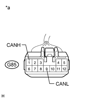
Text in Illustration *a Front view of wire harness connector
(to CAN No. 7 Junction Connector)
Disconnect the connector of the CAN No. 7 junction connector (G85).
-
Measure the resistance according to the value(s) in the table below.
Standard Resistance Tester Connection Switch Condition Specified Condition G85-1 (CANH) - G85-9 (CANL) Engine switch off 108 to 132 Ω
NG
REPAIR OR REPLACE CAN MS BUS MAIN WIRE OR CONNECTOR (CAN NO. 4 J/C - CAN NO. 7 J/C)
OK
-
-
CHECK FOR OPEN IN CAN MS BUS WIRE (CAN NO. 7 J/C - MAIN BODY ECU)
-
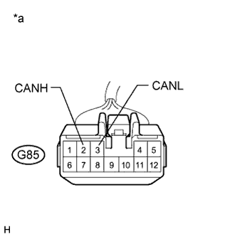
Text in Illustration *a Front view of wire harness connector
(to CAN No. 7 Junction Connector)
Measure the resistance according to the value(s) in the table below.
Standard Resistance Tester Connection Switch Condition Specified Condition G85-2 (CANH) - G85-3 (CANL) Engine switch off 108 to 132 Ω
NG
CHECK FOR OPEN IN CAN MS BUS WIRE (MAIN BODY ECU) Click here
OK
REPLACE CAN NO. 7 JUNCTION CONNECTOR
-
-
CHECK FOR OPEN IN CAN MS BUS WIRE (MAIN BODY ECU)
-
Reconnect the connector of the CAN No. 7 junction connector (G85).
-
Text in Illustration *a Front view of wire harness connector
(to Main Body ECU)
Disconnect the connector of the main body ECU.
-
Measure the resistance according to the value(s) in the table below.
Standard Resistance Tester Connection Switch Condition Specified Condition G50-16 (CANP) - G50-15 (CANN) Engine switch off 108 to 132 Ω
NG
REPAIR OR REPLACE CAN MS BUS MAIN WIRE OR CONNECTOR (CAN NO. 7 J/C - MAIN BODY ECU)
OK
REPLACE MAIN BODY ECU (DRIVER SIDE JUNCTION BLOCK) Click here
-
-
CHECK FOR SHORT IN CAN MS BUS WIRE
-
Text in Illustration *a Front view of wire harness connector
(to Certification ECU)
Disconnect the connector of the certification ECU.
-
Measure the resistance according to the value(s) in the table below.
Standard Resistance Tester Connection Switch Condition Specified Condition G20-27 (CANH) - G20-28 (CANL) Engine switch off 54 to 69 Ω
NG
CHECK FOR SHORT IN CAN MS BUS WIRE (CAN NO. 2 J/C RH - CERTIFICATION ECU) Click here
OK
REPLACE CERTIFICATION ECU (SMART KEY ECU ASSEMBLY)
-
-
CHECK FOR SHORT IN CAN MS BUS WIRE (CAN NO. 2 J/C RH - CERTIFICATION ECU)
-
Text in Illustration *a Rear view of wire harness connector
(to CAN No. 2 Junction Connector RH)
Disconnect the CAN branch wire connector (G70) from the CAN No. 2 junction connector RH (w/o earth terminal).
Note
-
Before disconnecting the connector, make a note of where it is connected.
-
Reconnect the connector to its original position.
-
-
Text in Illustration *a Front view of wire harness connector
(to Certification ECU)
Measure the resistance according to the value(s) in the table below.
Standard Resistance Tester Connection Switch Condition Specified Condition G20-27 (CANH) - G20-28 (CANL) Engine switch off 1 MΩ or higher
NG
REPAIR OR REPLACE CAN MS BUS BRANCH WIRE OR CONNECTOR (CAN NO. 2 J/C RH - CERTIFICATION ECU)
OK
-
-
CHECK FOR SHORT IN CAN MS BUS WIRE (CAN NO. 2 J/C RH - CAN NO. 5 J/C)
-
Reconnect the CAN branch wire connector (G70) to the CAN No. 2 junction connector RH (w/o earth terminal).
-
Text in Illustration *a Front view of wire harness connector
(to CAN No. 2 Junction Connector RH)
Disconnect the CAN main wire connector (G91) from the CAN No. 2 junction connector RH (w/o earth terminal).
Note
-
Before disconnecting the connector, make a note of where it is connected.
-
Reconnect the connector to its original position.
-
-
Text in Illustration *a Front view of wire harness connector
(to Certification ECU)
Measure the resistance according to the value(s) in the table below.
Standard Resistance Tester Connection Switch Condition Specified Condition G20-27 (CANH) - G20-28 (CANL) Engine switch off 108 to 132 Ω Result Result Proceed to The resistance is still below 54 Ω when the specified connectors are disconnected. (There is a short in the bus wires.) A The resistance becomes normal (between 108 to 132 Ω) when a connector is disconnected. (There is a short in the disconnected bus wires.) B
B
CHECK FOR SHORT IN CAN MS BUS WIRE (CAN NO. 5 J/C - CAN NO. 2 J/C RH) Click here
A
-
-
CHECK FOR SHORT IN CAN MS BUS WIRE (CAN NO. 2 J/C RH - CAN NO. 3 J/C)
-
Reconnect the CAN main wire connector (G91) to the CAN No. 2 junction connector RH (w/o earth terminal).
-
Text in Illustration *a Rear view of wire harness connector
(to CAN No. 2 Junction Connector RH)
Disconnect the CAN main wire connector (G71) from the CAN No. 2 junction connector RH (w/o earth terminal).
Note
-
Before disconnecting the connector, make a note of where it is connected.
-
Reconnect the connector to its original position.
-
-
Text in Illustration *a Front view of wire harness connector
(to Certification ECU)
Measure the resistance according to the value(s) in the table below.
Standard Resistance Tester Connection Switch Condition Specified Condition G20-27 (CANH) - G20-28 (CANL) Engine switch off 108 to 132 Ω Result Result Proceed to The resistance is still below 54 Ω when all the specified connectors are disconnected. (There is a short in the bus wires.) A The resistance becomes normal (between 108 to 132 Ω) when a connector is disconnected. (There is a short in the disconnected bus wires.) B
B
CHECK FOR SHORT IN CAN MS BUS WIRE (CAN NO. 3 J/C - CAN NO. 2 J/C RH) Click here
A
REPLACE CAN NO. 2 JUNCTION CONNECTOR RH
-
-
CHECK FOR SHORT IN CAN MS BUS WIRE (CAN NO. 5 J/C - CAN NO. 2 J/C RH)
-
Text in Illustration *a Front view of wire harness connector
(to CAN No. 5 Junction Connector)
Disconnect the connector of the CAN No. 5 junction connector (M22).
-
Measure the resistance according to the value(s) in the table below.
Standard Resistance Tester Connection Switch Condition Specified Condition M22-11 (CANH) - M22-22 (CANL) Engine switch off 1 MΩ or higher
NG
REPAIR OR REPLACE CAN MS BUS MAIN WIRE OR CONNECTOR (CAN NO. 2 J/C RH - CAN NO. 5 J/C)
OK
-
-
CHECK FOR SHORT IN CAN MS BUS WIRE (CAN NO. 5 J/C - COMBINATION METER)
-
Text in Illustration *a Front view of wire harness connector
(to CAN No. 5 Junction Connector)
Measure the resistance according to the value(s) in the table below.
Standard Resistance Tester Connection Switch Condition Specified Condition M22-10 (CANH) - M22-21 (CANL) Engine switch off 108 to 132 Ω
NG
CHECK FOR SHORT IN CAN MS BUS WIRE (COMBINATION METER) Click here
OK
-
-
CHECK FOR SHORT IN CAN MS BUS WIRE (CAN NO. 5 J/C - POWER SLIDE DOOR ECU RH)
-
Text in Illustration *a Front view of wire harness connector
(to Power Slide Door ECU)
Disconnect the connector of the power slide door ECU RH.
-
Text in Illustration *a Front view of wire harness connector
(to CAN No. 5 Junction Connector)
Measure the resistance according to the value(s) in the table below.
Standard Resistance Tester Connection Switch Condition Specified Condition M22-9 (CANH) - M22-20 (CANL) Engine switch off 1 MΩ or higher
NG
REPAIR OR REPLACE CAN MS BUS BRANCH WIRE OR CONNECTOR (CAN NO. 5 J/C - POWER SLIDE DOOR ECU RH)
OK
-
-
CHECK FOR SHORT IN CAN MS BUS WIRE (POWER SLIDE DOOR ECU RH)
-
Reconnect the CAN main wire connector (G91) to the CAN No. 2 junction connector RH (w/o earth terminal).
-
Reconnect the connector of the CAN No. 5 junction connector (M22).
-
Text in Illustration *a Front view of wire harness connector
(to Certification ECU)
Measure the resistance according to the value(s) in the table below.
Standard Resistance Tester Connection Switch Condition Specified Condition G20-27 (CANH) - G20-28 (CANL) Engine switch off 54 to 69 Ω
NG
REPLACE CAN NO. 5 JUNCTION CONNECTOR
OK
REPLACE SLIDE DOOR MOTOR UNIT RH (POWER SLIDE DOOR ECU RH) Click here
-
-
CHECK FOR SHORT IN CAN MS BUS WIRE (COMBINATION METER)
-
Text in Illustration *a Front view of wire harness connector
(to Combination Meter)
Disconnect the connector of the combination meter.
-
Text in Illustration *a Front view of wire harness connector
(to CAN No. 5 Junction Connector)
Measure the resistance according to the value(s) in the table below.
Standard Resistance Tester Connection Switch Condition Specified Condition M22-10 (CANH) - M22-21 (CANL) Engine switch off 1 MΩ or higher
NG
REPAIR OR REPLACE CAN MS BUS MAIN WIRE OR CONNECTOR (CAN NO. 5 J/C - COMBINATION METER)
OK
REPLACE COMBINATION METER Click here
-
-
CHECK FOR SHORT IN CAN MS BUS WIRE (CAN NO. 3 J/C - CAN NO. 2 J/C RH)
-
Reconnect the CAN main wire connector (G71) to the CAN No. 2 junction connector RH (w/o earth terminal).
-
Text in Illustration *a Front view of wire harness connector
(to CAN No. 3 Junction Connector)
Disconnect the connector of the CAN No. 3 junction connector (F10).
-
Measure the resistance according to the value(s) in the table below.
Standard Resistance Tester Connection Switch Condition Specified Condition F10-5 (CANH) - F10-16 (CANL) Engine switch off 108 to 132 Ω
NG
REPAIR OR REPLACE CAN MS BUS MAIN WIRE OR CONNECTOR (CAN NO. 2 J/C RH - CAN NO. 3 J/C)
OK
-
-
CHECK FOR SHORT IN CAN MS BUS WIRE (CAN NO. 3 J/C - CAN NO. 4 J/C)
-
Text in Illustration *a Front view of wire harness connector
(to CAN No. 3 Junction Connector)
Measure the resistance according to the value(s) in the table below.
Standard Resistance Tester Connection Switch Condition Specified Condition F10-6 (CANH) - F10-17 (CANL) Engine switch off 108 to 132 Ω
NG
CHECK FOR SHORT IN CAN MS BUS WIRE (CAN NO. 4 J/C - CAN NO. 3 J/C) Click here
OK
-
-
CHECK FOR SHORT IN CAN MS BUS WIRE (CAN NO. 3 J/C - CLEARANCE WARNING ECU)
-
Text in Illustration *a Front view of wire harness connector
(to Clearance Warning ECU)
Disconnect the connector of the clearance warning ECU.
-
Text in Illustration *a Front view of wire harness connector
(to CAN No. 3 Junction Connector)
Measure the resistance according to the value(s) in the table below.
Standard Resistance Tester Connection Switch Condition Specified Condition F10-7 (CANH) - F10-18 (CANL) Engine switch off 1 MΩ or higher
NG
REPAIR OR REPLACE CAN MS BUS BRANCH WIRE OR CONNECTOR (CAN NO. 3 J/C - CLEARANCE WARNING ECU)
OK
-
-
CHECK FOR SHORT IN CAN MS BUS WIRE (CLEARANCE WARNING ECU)
-
Reconnect the connector of the CAN No. 3 junction connector (F10).
-
Text in Illustration *a Front view of wire harness connector
(to Certification ECU)
Measure the resistance according to the value(s) in the table below.
Standard Resistance Tester Connection Switch Condition Specified Condition G20-27 (CANH) - G20-28 (CANL) Engine switch off 54 to 69 Ω
NG
REPLACE CAN NO. 3 JUNCTION CONNECTOR
OK
REPLACE CLEARANCE WARNING ECU Click here
-
-
CHECK FOR SHORT IN CAN MS BUS WIRE (CAN NO. 4 J/C - CAN NO. 3 J/C)
-
Reconnect the connector of the CAN No. 3 junction connector (F10).
-
Text in Illustration *a Front view of wire harness connector
(to CAN No. 4 Junction Connector)
Disconnect the connector of the CAN No. 4 junction connector (N28).
-
Measure the resistance according to the value(s) in the table below.
Standard Resistance Tester Connection Switch Condition Specified Condition N28-2 (CANH) - N28-10 (CANL) Engine switch off 108 to 132 Ω
NG
REPAIR OR REPLACE CAN MS BUS MAIN WIRE OR CONNECTOR (CAN NO. 3 J/C - CAN NO. 4 J/C)
OK
-
-
CHECK FOR SHORT IN CAN MS BUS WIRE (CAN NO. 4 J/C - CAN NO. 7 J/C)
-
Text in Illustration *a Front view of wire harness connector
(to CAN No. 4 Junction Connector)
Measure the resistance according to the value(s) in the table below.
Standard Resistance Tester Connection Switch Condition Specified Condition N28-1 (CANH) - N28-9 (CANL) Engine switch off 108 to 132 Ω
NG
CHECK FOR SHORT IN CAN MS BUS WIRE (CAN NO. 7 J/C - CAN NO. 4 J/C) Click here
OK
-
-
CHECK FOR SHORT IN CAN MS BUS WIRE (CAN NO. 4 J/C - POSITION CONTROL ECU)
-
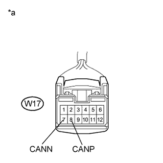
Text in Illustration *a Front view of wire harness connector
(to Position Control ECU)
Disconnect the connector of the position control ECU.
-
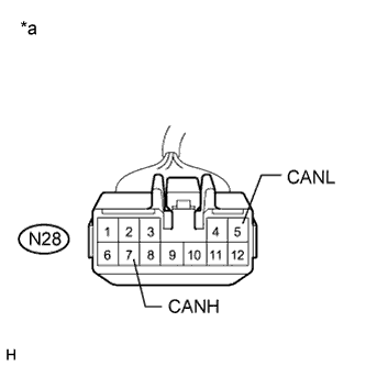
Text in Illustration *a Front view of wire harness connector
(to CAN No. 4 Junction Connector)
Measure the resistance according to the value(s) in the table below.
Standard Resistance Tester Connection Switch Condition Specified Condition N28-7 (CANH) - N28-5 (CANL) Engine switch off 1 MΩ or higher
NG
REPAIR OR REPLACE CAN MS BUS BRANCH WIRE OR CONNECTOR (CAN NO. 4 J/C - POSITION CONTROL ECU)
OK
-
-
CHECK FOR SHORT IN CAN MS BUS WIRE (CAN NO. 4 J/C - POWER SLIDE DOOR ECU LH)
-
Text in Illustration *a Front view of wire harness connector
(to Power Slide Door ECU LH)
Disconnect the connector of the power slide door ECU LH.
-
Text in Illustration *a Front view of wire harness connector
(to CAN No. 4 Junction Connector)
Measure the resistance according to the value(s) in the table below.
Standard Resistance Tester Connection Switch Condition Specified Condition N28-3 (CANH) - N28-11 (CANL) Engine switch off 1 MΩ or higher
NG
REPAIR OR REPLACE CAN MS BUS BRANCH WIRE OR CONNECTOR (CAN NO. 4 J/C - POWER SLIDE DOOR ECU LH)
OK
-
-
CHECK FOR SHORT IN CAN MS BUS WIRE (CAN NO. 4 J/C - POWER BACK DOOR ECU)
Tech Tips
For vehicles without the power back door system, go to the next step.
-
Text in Illustration *a Front view of wire harness connector
(to Power Back Door ECU)
Disconnect the connector of the power back door ECU.
-
Text in Illustration *a Front view of wire harness connector
(to CAN No. 4 Junction Connector)
Measure the resistance according to the value(s) in the table below.
Standard Resistance Tester Connection Switch Condition Specified Condition N28-8 (CANH) - N28-4 (CANL) Engine switch off 1 MΩ or higher
NG
REPAIR OR REPLACE CAN MS BUS BRANCH WIRE OR CONNECTOR (CAN NO. 4 J/C - POWER BACK DOOR ECU)
OK
-
-
CHECK FOR SHORT IN CAN MS BUS WIRE (CAN NO. 4 J/C - BACK DOOR CLOSER ECU)
-
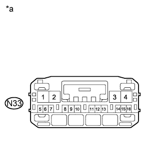
Text in Illustration *a Front view of wire harness connector
(to Back Door Closer ECU)
Disconnect the connector of the back door closer ECU.
-
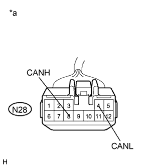
Text in Illustration *a Front view of wire harness connector
(to CAN No. 4 Junction Connector)
Measure the resistance according to the value(s) in the table below.
Standard Resistance Tester Connection Switch Condition Specified Condition N28-8 (CANH) - N28-4 (CANL) Engine switch off 1 MΩ or higher
NG
REPAIR OR REPLACE CAN MS BUS BRANCH WIRE OR CONNECTOR (CAN NO. 4 J/C - BACK DOOR CLOSER ECU)
OK
-
-
CHECK FOR SHORT IN CAN MS BUS WIRE (POWER SLIDE DOOR ECU LH)
-
Reconnect the connector of the power slide door ECU LH.
-
Reconnect the connector of the CAN No. 4 junction connector (N28).
-
Text in Illustration *a Front view of wire harness connector
(to Certification ECU)
Measure the resistance according to the value(s) in the table below.
Standard Resistance Tester Connection Switch Condition Specified Condition G20-27 (CANH) - G20-28 (CANL) Engine switch off 54 to 69 Ω
NG
REPLACE SLIDE DOOR MOTOR UNIT LH (POWER SLIDE DOOR ECU LH) Click here
OK
-
-
CHECK FOR SHORT IN CAN MS BUS WIRE (POSITION CONTROL ECU)
-
Reconnect the connector of the position control ECU.
-
Text in Illustration *a Front view of wire harness connector
(to Certification ECU)
Measure the resistance according to the value(s) in the table below.
Standard Resistance Tester Connection Switch Condition Specified Condition G20-27 (CANH) - G20-28 (CANL) Engine switch off 54 to 69 Ω Result Result Proceed to OK (w/ Power back door system) A OK (w/o Power back door system) B NG C
B
CHECK FOR SHORT IN CAN MS BUS WIRE (BACK DOOR CLOSER ECU) Click here
C
REPLACE POSITION CONTROL ECU (POSITION CONTROL ECU AND SWITCH) Click here
A
-
-
CHECK FOR SHORT IN CAN MS BUS WIRE (POWER BACK DOOR ECU)
-
Reconnect the connector of the power back door ECU.
-
Text in Illustration *a Front view of wire harness connector
(to Certification ECU)
Measure the resistance according to the value(s) in the table below.
Standard Resistance Tester Connection Switch Condition Specified Condition G20-27 (CANH) - G20-28 (CANL) Engine switch off 54 to 69 Ω
NG
REPLACE BACK DOOR MOTOR UNIT (POWER BACK DOOR ECU) Click here
OK
REPLACE CAN NO. 4 JUNCTION CONNECTOR
-
-
CHECK FOR SHORT IN CAN MS BUS WIRE (BACK DOOR CLOSER ECU)
-
Reconnect the connector of the back door closer ECU.
-
Text in Illustration *a Front view of wire harness connector
(to Certification ECU)
Measure the resistance according to the value(s) in the table below.
Standard Resistance Tester Connection Switch Condition Specified Condition G20-27 (CANH) - G20-28 (CANL) Engine switch off 54 to 69 Ω
NG
REPLACE MULTIPLEX NETWORK DOOR ECU (BACK DOOR CLOSER ECU) Click here
OK
REPLACE CAN NO. 4 JUNCTION CONNECTOR
-
-
CHECK FOR SHORT IN CAN MS BUS WIRE (CAN NO. 7 J/C - CAN NO. 4 J/C)
-
Reconnect the connector of the CAN No. 4 junction connector (N28).
-
Text in Illustration *a Front view of wire harness connector
(to CAN No. 7 Junction Connector)
Disconnect the connector of the CAN No. 7 junction connector (G85).
-
Measure the resistance according to the value(s) in the table below.
Standard Resistance Tester Connection Switch Condition Specified Condition G85-1 (CANH) - G85-9 (CANL) Engine switch off 108 to 132 Ω
NG
REPAIR OR REPLACE CAN MS BUS MAIN WIRE OR CONNECTOR (CAN NO. 4 J/C - CAN NO. 7 J/C)
OK
-
-
CHECK FOR SHORT IN CAN MS BUS WIRE (CAN NO. 7 J/C - MAIN BODY ECU)
-
Text in Illustration *a Front view of wire harness connector
(to CAN No. 7 Junction Connector)
Measure the resistance according to the value(s) in the table below.
Standard Resistance Tester Connection Switch Condition Specified Condition G85-2 (CANH) - G85-3 (CANL) Engine switch off 108 to 132 Ω
NG
CHECK FOR SHORT IN CAN MS BUS WIRE (MAIN BODY ECU) Click here
OK
-
-
CHECK FOR SHORT IN CAN MS BUS WIRE (CAN NO. 7 J/C - OUTER MIRROR CONTROL ECU)
-
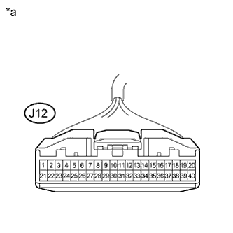
Text in Illustration *a Front view of wire harness connector
(to Outer Mirror Control ECU)
Disconnect the connector of the outer mirror control ECU.
-
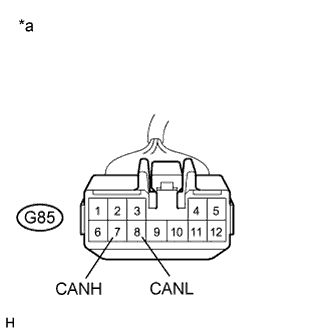
Text in Illustration *a Front view of wire harness connector
(to CAN No. 7 Junction Connector)
Measure the resistance according to the value(s) in the table below.
Standard Resistance Tester Connection Switch Condition Specified Condition G85-7 (CANH) - G85-8 (CANL) Engine switch off 1 MΩ or higher
NG
REPAIR OR REPLACE CAN MS BUS BRANCH WIRE OR CONNECTOR (CAN NO. 7 J/C - OUTER MIRROR CONTROL ECU)
OK
-
-
CHECK FOR SHORT IN CAN MS BUS WIRE (OUTER MIRROR CONTROL ECU)
-
Reconnect the connector of the outer mirror control ECU.
-
Reconnect the connector of the CAN No. 7 junction connector.
-
Text in Illustration *a Front view of wire harness connector
(to Certification ECU)
Measure the resistance according to the value(s) in the table below.
Standard Resistance Tester Connection Switch Condition Specified Condition G20-27 (CANH) - G20-28 (CANL) Engine switch off 54 to 69 Ω
B
REPLACE OUTER MIRROR CONTROL ECU Click here
A
REPLACE CAN NO. 7 JUNCTION CONNECTOR
-
-
CHECK FOR SHORT IN CAN MS BUS WIRE (MAIN BODY ECU)
-
Text in Illustration *a Front view of wire harness connector
(to Main Body ECU)
Disconnect the connector of the main body ECU.
-
Text in Illustration *a Front view of wire harness connector
(to CAN No. 7 Junction Connector)
Measure the resistance according to the value(s) in the table below.
Standard Resistance Tester Connection Switch Condition Specified Condition G85-2 (CANH) - G85-3 (CANL) Engine switch off 1 MΩ or higher
NG
REPAIR OR REPLACE CAN MS BUS MAIN WIRE OR CONNECTOR (CAN NO. 7 J/C - MAIN BODY ECU)
OK
REPLACE MAIN BODY ECU (DRIVER SIDE JUNCTION BLOCK) Click here
-
-
CHECK FOR SHORT TO +B, GND IN CAN MS BUS WIRE (CAN NO. 2 J/C RH - CERTIFICATION ECU)
-
Text in Illustration *1 DLC3 *a Rear view of wire harness connector
(to CAN No. 2 Junction Connector RH)
Disconnect the CAN branch wire connector (G70) from the CAN No. 2 junction connector RH (w/o earth terminal).
Note
-
Before disconnecting the connector, make a note of where it is connected.
-
Reconnect the connector to its original position.
-
-
Measure the resistance according to the value(s) in the table below.
Standard Resistance Tester Connection Condition Specified Condition G70-1 (CANH) - G8-16 (BAT) Cable disconnected from negative (-) battery terminal 6 kΩ or higher G70-2 (CANL) - G8-16 (BAT) Cable disconnected from negative (-) battery terminal 6 kΩ or higher G70-1 (CANH) - G8-4 (CG) Engine switch off 200 Ω or higher G70-2 (CANL) - G8-4 (CG) Engine switch off 200 Ω or higher Result Result Proceed to The resistance between terminals 6 (CANH) and 16 (BAT), or the resistance between 14 (CANL) and 16 (BAT) is still below 6 kΩ when all the specified connectors are disconnected from the CAN junction connector. (There is a short to +B in the bus wires.) A The resistance between terminals 6 (CANH) and 4 (CG), or the resistance between 14 (CANL) and 4 (CG) is still below 200 Ω when all the specified connectors are disconnected from the CAN junction connector. (There is a short to GND in the bus wires.) The resistance between terminals 6 (CANH) and 16 (BAT), or the resistance between 14 (CANL) and 16 (BAT) becomes normal (6 kΩ or higher) when a connector is disconnected from the CAN junction connector. (There is a short to +B in the disconnected bus wires.) B The resistance between terminals 6 (CANH) and 4 (CG), or the resistance between 14 (CANL) and 4 (CG)becomes normal (200 Ω or higher) when a connector is disconnected from the CAN junction connector. (There is a short to GND in the disconnected bus wires.)
B
CHECK FOR SHORT TO +B, GND IN CAN MS BUS WIRE (CAN NO. 2 J/C RH - CAN NO. 5 J/C) Click here
A
-
-
CHECK FOR SHORT TO +B, GND IN CAN MS BUS WIRE (CERTIFICATION ECU)
-
Text in Illustration *1 DLC3 *a Front view of wire harness connector
(to Certification ECU)
Disconnect the connector of the certification ECU.
-
Measure the resistance according to the value(s) in the table below.
Standard Resistance Tester Connection Condition Specified Condition G20-27 (CANH) - G8-16 (BAT) Cable disconnected from negative (-) battery terminal 6 kΩ or higher G20-28 (CANL) - G8-16 (BAT) Cable disconnected from negative (-) battery terminal 6 kΩ or higher G20-27 (CANH) - G8-4 (CG) Engine switch off 200 Ω or higher G20-28 (CANL) - G8-4 (CG) Engine switch off 200 Ω or higher
NG
REPAIR OR REPLACE CAN MS BUS BRANCH WIRE OR CONNECTOR (CAN NO. 2 J/C RH - CERTIFICATION ECU)
OK
REPLACE CERTIFICATION ECU (SMART KEY ECU ASSEMBLY)
-
-
CHECK FOR SHORT TO +B, GND IN CAN MS BUS WIRE (CAN NO. 2 J/C RH - CAN NO. 5 J/C)
-
Reconnect the CAN main wire connector (G70) to the CAN No. 2 junction connector RH (w/o earth terminal).
-
Disconnect the connector of the certification ECU.
-
Text in Illustration *a Rear view of wire harness connector
(to CAN No. 2 Junction Connector RH)
Disconnect the CAN main wire connector (G91) from the CAN No. 2 junction connector RH (w/o earth terminal).
-
Text in Illustration *1 DLC3 *a Front view of wire harness connector
(to Certification ECU)
Measure the resistance according to the value(s) in the table below.
Standard Resistance Tester Connection Condition Specified Condition G20-27 (CANH) - G8-16 (BAT) Cable disconnected from negative (-) battery terminal 6 kΩ or higher G20-28 (CANL) - G8-16 (BAT) Cable disconnected from negative (-) battery terminal 6 kΩ or higher G20-27 (CANH) - G8-4 (CG) Engine switch off 200 Ω or higher G20-28 (CANL) - G8-4 (CG) Engine switch off 200 Ω or higher Result Result Proceed to The resistance between terminals 6 (CANH) and 16 (BAT), or the resistance between 14 (CANL) and 16 (BAT) is still below 6 kΩ when all the specified connectors are disconnected from the CAN junction connector. (There is a short to +B in the bus wires.) A The resistance between terminals 6 (CANH) and 4 (CG), or the resistance between 14 (CANL) and 4 (CG) is still below 200 Ω when all the specified connectors are disconnected from the CAN junction connector. (There is a short to GND in the bus wires.) The resistance between terminals 6 (CANH) and 16 (BAT), or the resistance between 14 (CANL) and 16 (BAT) becomes normal (6 kΩ or higher) when a connector is disconnected from the CAN junction connector. (There is a short to +B in the disconnected bus wires.) B The resistance between terminals 6 (CANH) and 4 (CG), or the resistance between 14 (CANL) and 4 (CG) becomes normal (200 Ω or higher) when a connector is disconnected from the CAN junction connector. (There is a short to GND in the disconnected bus wires.)
B
CHECK FOR SHORT TO +B, GND IN CAN MS BUS WIRE (CAN NO. 5 J/C - CAN NO. 2 J/C RH) Click here
A
-
-
CHECK FOR SHORT TO +B, GND IN CAN MS BUS WIRE (CAN NO. 2 J/C RH - CAN NO. 3 J/C)
-
Reconnect the CAN main wire connector (G91) to the CAN No. 2 junction connector RH (w/o earth terminal).
-
Text in Illustration *a Rear view of wire harness connector
(to CAN No. 2 Junction Connector RH)
Disconnect the CAN main wire connector (G71) from the CAN No. 2 junction connector RH (w/o earth terminal).
Note
-
Before disconnecting the connector, make a note of where it is connected.
-
Reconnect the connector to its original position.
-
-
Text in Illustration *1 DLC3 *a Front view of wire harness connector
(to Certification ECU)
Measure the resistance according to the value(s) in the table below.
Standard Resistance Tester Connection Condition Specified Condition G20-27 (CANH) - G8-16 (BAT) Cable disconnected from negative (-) battery terminal 6 kΩ or higher G20-28 (CANL) - G8-16 (BAT) Cable disconnected from negative (-) battery terminal 6 kΩ or higher G20-27 (CANH) - G8-4 (CG) Engine switch off 200 Ω or higher G20-28 (CANL) - G8-4 (CG) Engine switch off 200 Ω or higher Result Result Proceed to The resistance between terminals 6 (CANH) and 16 (BAT), or the resistance between 14 (CANL) and 16 (BAT) is still below 6 kΩ when all the specified connectors are disconnected from the CAN junction connector. (There is a short to +B in the bus wires.) A The resistance between terminals 6 (CANH) and 4 (CG), or the resistance between 14 (CANL) and 4 (CG) is still below 200 Ω when all the specified connectors are disconnected from the CAN junction connector. (There is a short to GND in the bus wires.) The resistance between terminals 6 (CANH) and 16 (BAT), or the resistance between 14 (CANL) and 16 (BAT) becomes normal (6 kΩ or higher) when a connector is disconnected from the CAN junction connector. (There is a short to +B in the disconnected bus wires.) B The resistance between terminals 6 (CANH) and 4 (CG), or the resistance between 14 (CANL) and 4 (CG) becomes normal (200 Ω or higher) when a connector is disconnected from the CAN junction connector. (There is a short to GND in the disconnected bus wires.)
B
CHECK FOR SHORT TO +B, GND IN CAN MS BUS WIRE (CAN NO. 3 J/C - CAN NO. 2 J/C RH) Click here
A
REPLACE CAN NO. 2 JUNCTION CONNECTOR RH
-
-
CHECK FOR SHORT TO +B, GND IN CAN MS BUS WIRE (CAN NO. 5 J/C - CAN NO. 2 J/C RH)
-
Reconnect the CAN main wire connector (G91) to the CAN No. 2 junction connector RH (w/o earth terminal).
-
Text in Illustration *1 DLC3 *a Front view of wire harness connector
(to CAN No. 5 Junction Connector)
Disconnect the connector of the CAN No. 5 junction connector (M22).
-
Measure the resistance according to the value(s) in the table below.
Standard Resistance Tester Connection Condition Specified Condition M22-11 (CANH) - G8-16 (BAT) Cable disconnected from negative (-) battery terminal 6 kΩ or higher M22-22 (CANL) - G8-16 (BAT) Cable disconnected from negative (-) battery terminal 6 kΩ or higher M22-11 (CANH) - G8-4 (CG) Engine switch off 200 Ω or higher M22-22 (CANL) - G8-4 (CG) Engine switch off 200 Ω or higher
NG
REPAIR OR REPLACE CAN MS BUS MAIN WIRE OR CONNECTOR (CAN NO. 2 J/C RH - CAN NO. 5 J/C)
OK
-
-
CHECK FOR SHORT TO +B, GND IN CAN MS BUS WIRE (CAN NO. 5 J/C - COMBINATION METER)
-
Text in Illustration *1 DLC3 *a Front view of wire harness connector
(to CAN No. 5 Junction Connector)
Measure the resistance according to the value(s) in the table below.
Standard Resistance Tester Connection Condition Specified Condition M22-10 (CANH) - G8-16 (BAT) Cable disconnected from negative (-) battery terminal 6 kΩ or higher M22-21 (CANL) - G8-16 (BAT) Cable disconnected from negative (-) battery terminal 6 kΩ or higher M22-10 (CANH) - G8-4 (CG) Engine switch off 200 Ω or higher M22-21 (CANL) - G8-4 (CG) Engine switch off 200 Ω or higher
NG
CHECK FOR SHORT TO +B, GND IN CAN MS BUS WIRE (COMBINATION METER) Click here
OK
-
-
CHECK FOR SHORT TO +B, GND IN CAN MS BUS WIRE (CAN NO. 5 J/C - POWER SLIDE DOOR ECU RH)
-
Text in Illustration *1 DLC3 *a Front view of wire harness connector
(to CAN No. 5 Junction Connector)
Measure the resistance according to the value(s) in the table below.
Standard Resistance Tester Connection Condition Specified Condition M22-9 (CANH) - G8-16 (BAT) Cable disconnected from negative (-) battery terminal 6 kΩ or higher M22-20 (CANL) - G8-16 (BAT) Cable disconnected from negative (-) battery terminal 6 kΩ or higher M22-9 (CANH) - G8-4 (CG) Engine switch off 200 Ω or higher M22-20 (CANL) - G8-4 (CG) Engine switch off 200 Ω or higher
NG
CHECK FOR SHORT TO +B, GND IN CAN MS BUS WIRE (POWER SLIDE DOOR ECU RH) Click here
OK
REPLACE CAN NO. 5 JUNCTION CONNECTOR
-
-
CHECK FOR SHORT TO +B, GND IN CAN MS BUS WIRE (COMBINATION METER)
-
Text in Illustration *a Front view of wire harness connector
(to Combination Meter)
Disconnect the connector of the combination meter.
-
Text in Illustration *1 DLC3 *a Front view of wire harness connector
(to CAN No. 5 Junction Connector)
Measure the resistance according to the value(s) in the table below.
Standard Resistance Tester Connection Condition Specified Condition M22-10 (CANH) - G8-16 (BAT) Cable disconnected from negative (-) battery terminal 6 kΩ or higher M22-21 (CANL) - G8-16 (BAT) Cable disconnected from negative (-) battery terminal 6 kΩ or higher M22-10 (CANH) - G8-4 (CG) Engine switch off 200 Ω or higher M22-21 (CANL) - G8-4 (CG) Engine switch off 200 Ω or higher
NG
REPAIR OR REPLACE CAN MS BUS MAIN WIRE OR CONNECTOR (CAN NO. 5 J/C - COMBINATION METER)
OK
REPLACE COMBINATION METER Click here
-
-
CHECK FOR SHORT TO +B, GND IN CAN MS BUS WIRE (POWER SLIDE DOOR ECU RH)
-
Text in Illustration *a Front view of wire harness connector
(to Power Slide Door ECU RH)
Disconnect the connector of the power slide door ECU RH.
-
Text in Illustration *1 DLC3 *a Front view of wire harness connector
(to CAN No. 5 Junction Connector)
Measure the resistance according to the value(s) in the table below.
Standard Resistance Tester Connection Condition Specified Condition M22-9 (CANH) - G8-16 (BAT) Cable disconnected from negative (-) battery terminal 6 kΩ or higher M22-20 (CANL) - G8-16 (BAT) Cable disconnected from negative (-) battery terminal 6 kΩ or higher M22-9 (CANH) - G8-4 (CG) Engine switch off 200 Ω or higher M22-20 (CANL) - G8-4 (CG) Engine switch off 200 Ω or higher
NG
REPAIR OR REPLACE CAN MS BUS BRANCH WIRE OR CONNECTOR (CAN NO. 5 J/C - POWER SLIDE DOOR ECU RH)
OK
REPLACE SLIDE DOOR MOTOR UNIT RH (POWER SLIDE DOOR ECU RH) Click here
-
-
CHECK FOR SHORT TO +B, GND IN CAN MS BUS WIRE (CAN NO. 3 J/C - CAN NO. 2 J/C RH)
-
Reconnect the CAN main wire connector (G71) to the CAN No. 2 junction connector RH (w/o earth terminal).
-
Text in Illustration *1 DLC3 *a Front view of wire harness connector
(to CAN No. 3 Junction Connector)
Disconnect the connector of the CAN No. 3 junction connector.
-
Measure the resistance according to the value(s) in the table below.
Standard Resistance Tester Connection Condition Specified Condition F10-5 (CANH) - G8-16 (BAT) Cable disconnected from negative (-) battery terminal 6 kΩ or higher F10-16 (CANL) - G8-16 (BAT) Cable disconnected from negative (-) battery terminal 6 kΩ or higher F10-5 (CANH) - G8-4 (CG) Engine switch off 200 Ω or higher F10-16 (CANL) - G8-4 (CG) Engine switch off 200 Ω or higher
NG
REPAIR OR REPLACE CAN MS BUS MAIN WIRE OR CONNECTOR (CAN NO. 2 J/C RH - CAN NO. 3 J/C)
OK
-
-
CHECK FOR SHORT TO +B, GND IN CAN MS BUS WIRE (CAN NO. 3 J/C - CAN NO. 4 J/C)
-
Text in Illustration *1 DLC3 *a Front view of wire harness connector
(to CAN No. 3 Junction Connector)
Measure the resistance according to the value(s) in the table below.
Standard Resistance Tester Connection Condition Specified Condition F10-6 (CANH) - G8-16 (BAT) Cable disconnected from negative (-) battery terminal 6 kΩ or higher F10-17 (CANL) - G8-16 (BAT) Cable disconnected from negative (-) battery terminal 6 kΩ or higher F10-6 (CANH) - G8-4 (CG) Engine switch off 200 Ω or higher F10-17 (CANL) - G8-4 (CG) Engine switch off 200 Ω or higher
NG
CHECK FOR SHORT TO +B, GND IN CAN MS BUS WIRE (CAN NO. 4 J/C - CAN NO. 3 J/C) Click here
OK
-
-
CHECK FOR SHORT TO +B, GND IN CAN MS BUS WIRE (CAN NO. 3 J/C - CLEARANCE WARNING ECU)
-
Text in Illustration *1 DLC3 *a Front view of wire harness connector
(to CAN No. 3 Junction Connector)
Measure the resistance according to the value(s) in the table below.
Standard Resistance Tester Connection Condition Specified Condition F10-7 (CANH) - G8-16 (BAT) Cable disconnected from negative (-) battery terminal 6 kΩ or higher F10-18 (CANL) - G8-16 (BAT) Cable disconnected from negative (-) battery terminal 6 kΩ or higher F10-7 (CANH) - G8-4 (CG) Engine switch off 200 Ω or higher F10-18 (CANL) - G8-4 (CG) Engine switch off 200 Ω or higher
NG
CHECK FOR SHORT TO +B, GND IN CAN MS BUS WIRE (CLEARANCE WARNING ECU) Click here
OK
REPLACE CAN NO. 3 JUNCTION CONNECTOR
-
-
CHECK FOR SHORT TO +B, GND IN CAN MS BUS WIRE (CLEARANCE WARNING ECU)
-
Text in Illustration *a Front view of wire harness connector
(to Clearance Warning ECU)
Disconnect the connector of the clearance warning ECU.
-
Text in Illustration *1 DLC3 *a Front view of wire harness connector
(to CAN No. 3 Junction Connector)
Measure the resistance according to the value(s) in the table below.
Standard Resistance Tester Connection Condition Specified Condition F10-7 (CANH) - G8-16 (BAT) Cable disconnected from negative (-) battery terminal 6 kΩ or higher F10-18 (CANL) - G8-16 (BAT) Cable disconnected from negative (-) battery terminal 6 kΩ or higher F10-7 (CANH) - G8-4 (CG) Engine switch off 200 Ω or higher F10-18 (CANL) - G8-4 (CG) Engine switch off 200 Ω or higher
NG
REPAIR OR REPLACE CAN MS BUS BRANCH WIRE OR CONNECTOR (CAN NO. 3 J/C - CLEARANCE WARNING ECU)
OK
REPLACE CLEARANCE WARNING ECU Click here
-
-
CHECK FOR SHORT TO +B, GND IN CAN MS BUS WIRE (CAN NO. 4 J/C - CAN NO. 3 J/C)
-
Reconnect the connector of the CAN No. 3 junction connector (F10).
-
Text in Illustration *1 DLC3 *a Front view of wire harness connector
(to CAN No. 4 Junction Connector)
Disconnect the connector of the CAN No. 4 junction connector (N28).
-
Measure the resistance according to the value(s) in the table below.
Standard Resistance Tester Connection Condition Specified Condition N28-2 (CANH) - G8-16 (BAT) Cable disconnected from negative (-) battery terminal 6 kΩ or higher N28-10 (CANL) - G8-16 (BAT) Cable disconnected from negative (-) battery terminal 6 kΩ or higher N28-2 (CANH) - G8-4 (CG) Engine switch off 200 Ω or higher N28-10 (CANL) - G8-4 (CG) Engine switch off 200 Ω or higher
NG
REPAIR OR REPLACE CAN MS BUS MAIN WIRE OR CONNECTOR (CAN NO. 3 J/C - CAN NO. 4 J/C)
OK
-
-
CHECK FOR SHORT TO +B, GND IN CAN MS BUS WIRE (CAN NO. 4 J/C - CAN NO. 7 J/C)
-
Text in Illustration *1 DLC3 *a Front view of wire harness connector
(to CAN No. 4 Junction Connector)
Measure the resistance according to the value(s) in the table below.
Standard Resistance Tester Connection Condition Specified Condition N28-1 (CANH) - G8-16 (BAT) Cable disconnected from negative (-) battery terminal 6 kΩ or higher N28-9 (CANL) - G8-16 (BAT) Cable disconnected from negative (-) battery terminal 6 kΩ or higher N28-1 (CANH) - G8-4 (CG) Engine switch off 200 Ω or higher N28-9 (CANL) - G8-4 (CG) Engine switch off 200 Ω or higher
NG
CHECK FOR SHORT TO +B, GND IN CAN MS BUS WIRE (CAN NO. 7 J/C - CAN NO. 4 J/C) Click here
OK
-
-
CHECK FOR SHORT TO +B, GND IN CAN MS BUS WIRE (CAN NO. 4 J/C - POSITION CONTROL ECU)
-
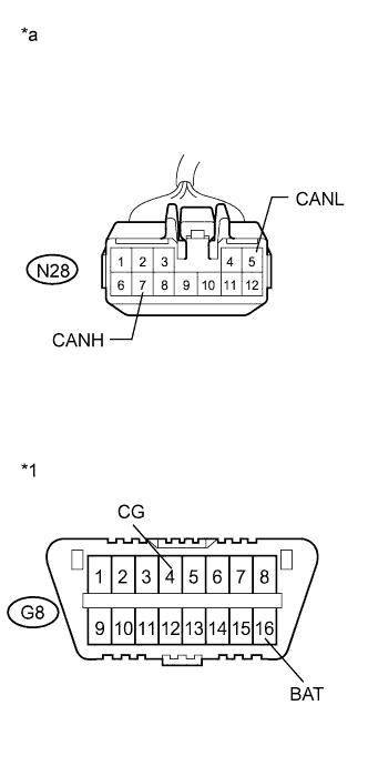
Text in Illustration *1 DLC3 *a Front view of wire harness connector
(to CAN No. 4 Junction Connector)
Measure the resistance according to the value(s) in the table below.
Standard Resistance Tester Connection Condition Specified Condition N28-7 (CANH) - G8-16 (BAT) Cable disconnected from negative (-) battery terminal 6 kΩ or higher N28-5 (CANL) - G8-16 (BAT) Cable disconnected from negative (-) battery terminal 6 kΩ or higher N28-7 (CANH) - G8-4 (CG) Engine switch off 200 Ω or higher N28-5 (CANL) - G8-4 (CG) Engine switch off 200 Ω or higher
NG
CHECK FOR SHORT TO +B, GND IN CAN MS BUS WIRE (POSITION CONTROL ECU) Click here
OK
-
-
CHECK FOR SHORT TO +B, GND IN CAN MS BUS WIRE (CAN NO. 4 J/C - POWER BACK DOOR ECU)
Tech Tips
For vehicles without the power back door system, go to the next step.
-
Text in Illustration *1 DLC3 *a Front view of wire harness connector
(to CAN No. 4 Junction Connector)
Measure the resistance according to the value(s) in the table below.
Standard Resistance Tester Connection Condition Specified Condition N28-8 (CANH) - G8-16 (BAT) Cable disconnected from negative (-) battery terminal 6 kΩ or higher N28-4 (CANL) - G8-16 (BAT) Cable disconnected from negative (-) battery terminal 6 kΩ or higher N28-8 (CANH) - G8-4 (CG) Engine switch off 200 Ω or higher N28-4 (CANL) - G8-4 (CG) Engine switch off 200 Ω or higher
B
CHECK FOR SHORT TO +B, GND IN CAN MS BUS WIRE (POWER BACK DOOR ECU) Click here
OK
-
-
CHECK FOR SHORT TO +B, GND IN CAN MS BUS WIRE (CAN NO. 4 J/C - BACK DOOR CLOSER ECU)
-
Text in Illustration *1 DLC3 *a Front view of wire harness connector
(to CAN No. 4 Junction Connector)
Measure the resistance according to the value(s) in the table below.
Standard Resistance Tester Connection Condition Specified Condition N28-8 (CANH) - G8-16 (BAT) Cable disconnected from negative (-) battery terminal 6 kΩ or higher N28-4 (CANL) - G8-16 (BAT) Cable disconnected from negative (-) battery terminal 6 kΩ or higher N28-8 (CANH) - G8-4 (CG) Engine switch off 200 Ω or higher N28-4 (CANL) - G8-4 (CG) Engine switch off 200 Ω or higher
NG
CHECK FOR SHORT TO +B, GND IN CAN MS BUS WIRE (BACK DOOR CLOSER ECU) Click here
OK
-
-
CHECK FOR SHORT TO +B, GND IN CAN MS BUS WIRE (CAN NO. 4 J/C - POWER SLIDE DOOR ECU LH)
-
Text in Illustration *1 DLC3 *a Front view of wire harness connector
(to CAN No. 4 Junction Connector)
Measure the resistance according to the value(s) in the table below.
Standard Resistance Tester Connection Condition Specified Condition N28-3 (CANH) - G8-16 (BAT) Cable disconnected from negative (-) battery terminal 6 kΩ or higher N28-11 (CANL) - G8-16 (BAT) Cable disconnected from negative (-) battery terminal 6 kΩ or higher N28-3 (CANH) - G8-4 (CG) Engine switch off 200 Ω or higher N28-11 (CANL) - G8-4 (CG) Engine switch off 200 Ω or higher
NG
CHECK FOR SHORT TO +B, GND IN CAN MS BUS WIRE (POWER SLIDE DOOR ECU LH) Click here
OK
REPLACE CAN NO. 4 JUNCTION CONNECTOR
-
-
CHECK FOR SHORT TO +B, GND IN CAN MS BUS WIRE (POSITION CONTROL ECU)
-
Text in Illustration *a Front view of wire harness connector
(to Position Control ECU)
Disconnect the connector of the position control ECU.
-
Text in Illustration *1 DLC3 *a Front view of wire harness connector
(to CAN No. 4 Junction Connector)
Measure the resistance according to the value(s) in the table below.
Standard Resistance Tester Connection Condition Specified Condition N28-7 (CANH) - G8-16 (BAT) Cable disconnected from negative (-) battery terminal 6 kΩ or higher N28-5 (CANL) - G8-16 (BAT) Cable disconnected from negative (-) battery terminal 6 kΩ or higher N28-7 (CANH) - G8-4 (CG) Engine switch off 200 Ω or higher N28-5 (CANL) - G8-4 (CG) Engine switch off 200 Ω or higher
NG
REPAIR OR REPLACE CAN MS BUS BRANCH WIRE OR CONNECTOR (CAN NO. 4 J/C - POSITION CONTROL ECU)
OK
REPLACE POSITION CONTROL ECU AND SWITCH (POSITION CONTROL ECU) Click here
-
-
CHECK FOR SHORT TO +B, GND IN CAN MS BUS WIRE (POWER SLIDE DOOR ECU LH)
-
Text in Illustration *a Front view of wire harness connector
(to Power Slide Door ECU LH)
Disconnect the connector of the power slide door ECU LH.
-
Text in Illustration *1 DLC3 *a Front view of wire harness connector
(to CAN No. 4 Junction Connector)
Measure the resistance according to the value(s) in the table below.
Standard Resistance Tester Connection Condition Specified Condition N28-3 (CANH) - G8-16 (BAT) Cable disconnected from negative (-) battery terminal 6 kΩ or higher N28-11 (CANL) - G8-16 (BAT) Cable disconnected from negative (-) battery terminal 6 kΩ or higher N28-3 (CANH) - G8-4 (CG) Engine switch off 200 Ω or higher N28-11 (CANL) - G8-4 (CG) Engine switch off 200 Ω or higher
NG
REPAIR OR REPLACE CAN MS BUS BRANCH WIRE OR CONNECTOR (CAN NO. 4 J/C - POWER SLIDE DOOR ECU LH)
OK
REPLACE SLIDE DOOR MOTOR UNIT LH (POWER SLIDE DOOR ECU LH) Click here
-
-
CHECK FOR SHORT TO +B, GND IN CAN MS BUS WIRE (POWER BACK DOOR ECU)
-
Text in Illustration *a Front view of wire harness connector
(to Power Back Door ECU)
Disconnect the connector of the power back door ECU.
-
Text in Illustration *1 DLC3 *a Front view of wire harness connector
(to CAN No. 4 Junction Connector)
Measure the resistance according to the value(s) in the table below.
Standard Resistance Tester Connection Condition Specified Condition N28-8 (CANH) - G8-16 (BAT) Cable disconnected from negative (-) battery terminal 6 kΩ or higher N28-4 (CANL) - G8-16 (BAT) Cable disconnected from negative (-) battery terminal 6 kΩ or higher N28-8 (CANH) - G8-4 (CG) Engine switch off 200 Ω or higher N28-4 (CANL) - G8-4 (CG) Engine switch off 200 Ω or higher
NG
REPAIR OR REPLACE CAN MS BUS BRANCH WIRE OR CONNECTOR (CAN NO. 4 J/C - POWER BACK DOOR ECU)
OK
REPLACE BACK DOOR MOTOR UNIT (POWER BACK DOOR ECU) Click here
-
-
CHECK FOR SHORT TO +B, GND IN CAN MS BUS WIRE (BACK DOOR CLOSER ECU)
-
Text in Illustration *a Front view of wire harness connector
(to Back Door Closer ECU)
Disconnect the connector of the back door closer ECU.
-
Text in Illustration *1 DLC3 *a Front view of wire harness connector
(to CAN No. 4 Junction Connector)
Measure the resistance according to the value(s) in the table below.
Standard Resistance Tester Connection Condition Specified Condition N28-8 (CANH) - G8-16 (BAT) Cable disconnected from negative (-) battery terminal 6 kΩ or higher N28-4 (CANL) - G8-16 (BAT) Cable disconnected from negative (-) battery terminal 6 kΩ or higher N28-8 (CANH) - G8-4 (CG) Engine switch off 200 Ω or higher N28-4 (CANL) - G8-4 (CG) Engine switch off 200 Ω or higher
NG
REPAIR OR REPLACE CAN MS BUS BRANCH WIRE OR CONNECTOR (CAN NO. 4 J/C - BACK DOOR CLOSER ECU)
OK
REPLACE MULTIPLEX NETWORK DOOR ECU (BACK DOOR CLOSER ECU) Click here
-
-
CHECK FOR SHORT TO +B, GND IN CAN MS BUS WIRE (CAN NO. 7 J/C - CAN NO. 4 J/C)
-
Reconnect the connector of the CAN No. 4 junction connector (N28).
-
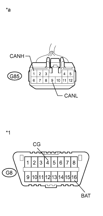
Text in Illustration *1 DLC3 *a Front view of wire harness connector
(to CAN No. 7 Junction Connector)
Disconnect the connector of the CAN No. 7 junction connector (G85).
-
Measure the resistance according to the value(s) in the table below.
Standard Resistance Tester Connection Condition Specified Condition G85-1 (CANH) - G8-16 (BAT) Cable disconnected from negative (-) battery terminal 6 kΩ or higher G85-9 (CANL) - G8-16 (BAT) Cable disconnected from negative (-) battery terminal 6 kΩ or higher G85-1 (CANH) - G8-4 (CG) Engine switch off 200 Ω or higher G85-9 (CANL) - G8-4 (CG) Engine switch off 200 Ω or higher
NG
REPAIR OR REPLACE CAN MS BUS MAIN WIRE OR CONNECTOR (CAN NO. 4 J/C - CAN NO. 7 J/C)
OK
-
-
CHECK FOR SHORT TO +B, GND IN CAN MS BUS WIRE (CAN NO. 7 J/C - MAIN BODY ECU)
-
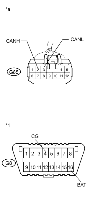
Text in Illustration *1 DLC3 *a Front view of wire harness connector
(to CAN No. 7 Junction Connector)
Measure the resistance according to the value(s) in the table below.
Standard Resistance Tester Connection Condition Specified Condition G85-2 (CANH) - G8-16 (BAT) Cable disconnected from negative (-) battery terminal 6 kΩ or higher G85-3 (CANL) - G8-16 (BAT) Cable disconnected from negative (-) battery terminal 6 kΩ or higher G85-2 (CANH) - G8-4 (CG) Engine switch off 200 Ω or higher G85-3 (CANL) - G8-4 (CG) Engine switch off 200 Ω or higher
NG
CHECK FOR SHORT TO +B, GND IN CAN MS BUS WIRE (MAIN BODY ECU) Click here
OK
-
-
CHECK FOR SHORT TO +B, GND IN CAN MS BUS WIRE (CAN NO. 7 J/C - OUTER MIRROR CONTROL ECU)
-
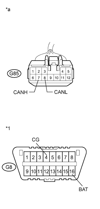
Text in Illustration *1 DLC3 *a Front view of wire harness connector
(to CAN No. 7 Junction Connector)
Measure the resistance according to the value(s) in the table below.
Standard Resistance Tester Connection Condition Specified Condition G85-7 (CANH) - G8-16 (BAT) Cable disconnected from negative (-) battery terminal 6 kΩ or higher G85-8 (CANL) - G8-16 (BAT) Cable disconnected from negative (-) battery terminal 6 kΩ or higher G85-7 (CANH) - G8-4 (CG) Engine switch off 200 Ω or higher G85-8 (CANL) - G8-4 (CG) Engine switch off 200 Ω or higher
NG
CHECK FOR SHORT TO +B, GND IN CAN MS BUS WIRE (OUTER MIRROR CONTROL ECU) Click here
OK
REPLACE CAN NO. 7 JUNCTION CONNECTOR
-
-
CHECK FOR SHORT TO +B, GND IN CAN MS BUS WIRE (MAIN BODY ECU)
-
Text in Illustration *a Front view of wire harness connector
(to Main Body ECU)
Disconnect the connector of the main body ECU.
-
Text in Illustration *1 DLC3 *a Front view of wire harness connector
(to CAN No. 7 Junction Connector)
Measure the resistance according to the value(s) in the table below.
Standard Resistance Tester Connection Condition Specified Condition G85-2 (CANH) - G8-16 (BAT) Cable disconnected from negative (-) battery terminal 6 kΩ or higher G85-3 (CANL) - G8-16 (BAT) Cable disconnected from negative (-) battery terminal 6 kΩ or higher G85-2 (CANH) - G8-4 (CG) Engine switch off 200 Ω or higher G85-3 (CANL) - G8-4 (CG) Engine switch off 200 Ω or higher
NG
REPAIR OR REPLACE CAN MS BUS MAIN WIRE OR CONNECTOR (CAN NO. 7 J/C - MAIN BODY ECU)
OK
REPLACE MAIN BODY ECU (DRIVER SIDE JUNCTION BLOCK) Click here
-
-
CHECK FOR SHORT TO +B, GND IN CAN MS BUS WIRE (OUTER MIRROR CONTROL ECU)
-
Text in Illustration *a Front view of wire harness connector
(to Outer Mirror Control ECU)
Disconnect the connector of the outer mirror control ECU.
-
Text in Illustration *1 DLC3 *a Front view of wire harness connector
(to CAN No. 7 Junction Connector)
Measure the resistance according to the value(s) in the table below.
Standard Resistance Tester Connection Condition Specified Condition G85-7 (CANH) - G8-16 (BAT) Cable disconnected from negative (-) battery terminal 6 kΩ or higher G85-8 (CANL) - G8-16 (BAT) Cable disconnected from negative (-) battery terminal 6 kΩ or higher G85-7 (CANH) - G8-4 (CG) Engine switch off 200 Ω or higher G85-8 (CANL) - G8-4 (CG) Engine switch off 200 Ω or higher
NG
REPAIR OR REPLACE CAN MS BUS BRANCH WIRE OR CONNECTOR (CAN NO. 7 J/C - OUTER MIRROR CONTROL ECU)
OK
REPLACE OUTER MIRROR CONTROL ECU Click here
-