CAN COMMUNICATION SYSTEM DIAGNOSIS SYSTEM

-
ECUS OR SENSORS WHICH COMMUNICATE THROUGH CAN COMMUNICATION SYSTEM
-
CAN No. 1 Bus
-
ECM
-
Main body ECU
-
Combination meter
-
Power steering ECU
-
Air conditioning amplifier
-
Center airbag sensor assembly
-
Brake actuator (Skid control ECU)
-
Steering angle sensor
-
Yaw rate and acceleration sensor
-
AFS ECU (for LHD)
-
AFS ECU (for RHD)*1
-
Navigation ECU sub-assembly (for LHD)*2
Tech Tips
-
*1: w/ AFS
-
*2: w/ Navigation system
-
-
-
CAN MS Bus
-
Certification ECU (Smart key ECU assembly)
-
Slide door motor unit LH (Power slide door ECU LH)
-
Slide door motor unit RH (Power slide door ECU RH) (for LHD)
-
Slide door motor unit RH (Power slide door ECU RH) (for RHD)*3
-
Back door motor unit (Power back door ECU)*4
-
Multiplex network door ECU (back door closer ECU)*5
-
Clearance warning ECU
-
Outer mirror control ECU
-
Position control ECU and switch (Position control ECU) (for LHD)
-
Position control ECU and switch (Position control ECU) (for RHD)*6
Tech Tips
-
*3: w/ Power slide door RH
-
*4: w/ Power back door system
-
*5: w/o Power back door system
-
*6: w/ Seat position memory
-
-
-
-
CHECK FOR INSTALLED SYSTEMS (ECUS AND SENSORS) THAT ADOPT CAN COMMUNICATION
-
Systems (ECUs and sensors) that adopt CAN communication vary depending on the options that the vehicle is equipped with. Check which systems (ECUs and sensors) are installed on the vehicle.
ECU/Sensor Name Intelligent Tester Display Applicability ECM Engine
ECT
Installed on all vehicles Main body ECU Main Body Installed on all vehicles Combination meter Combination Meter Installed on all vehicles Power steering ECU EPS Installed on all vehicles Air conditioning amplifier Air Conditioner Installed on all vehicles Center airbag sensor assembly SRS Airbag Installed on all vehicles Brake actuator (Skid control ECU) ABS/VSC/TRC Installed on all vehicles Steering angle sensor Steering Angle Sensor Installed on all vehicles Yaw rate and acceleration sensor Yaw Rate / Deceleration Sensor Installed on all vehicles Certification ECU (Smart key ECU assembly) Entry & Start / Wireless Tuner Installed on all vehicles Slide door motor unit LH (Power slide door ECU LH) Rear Left Door Installed on all vehicles Slide door motor unit RH (Power slide door ECU RH) Rear Right Door w/ Power slide door RH (for RHD)
Installed on all vehicles (for LHD)
Back door motor unit (Power back door ECU) Power Back Door w/ Power back door system Multiplex network door ECU (back door closer ECU) Back Door w/o Power back door system Clearance warning ECU Clearance Sonar Installed on all vehicles Outer mirror control ECU Drive Door/Mirror Installed on all vehicles Position control ECU and switch (Position control ECU) Driver Seat w/ Seat position memory (for RHD)
Installed on all vehicles (for LHD)
AFS ECU AFS/HL AutoLeveling w/ AFS (for RHD)
Installed on all vehicles (for LHD)
Navigation ECU sub-assembly AVN1 w/ Navigation system (for LHD)
-
-
BUS CHECK (COMMUNICATION MALFUNCTION DTC)
Tech Tips
Only CAN communication system DTCs for each ECU can be displayed on the intelligent tester.
-
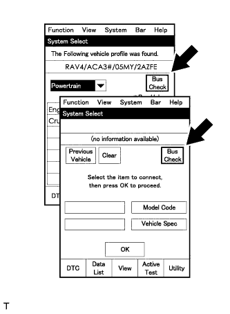
Select "Bus Check" from the "System Select" screen on the intelligent tester.
-
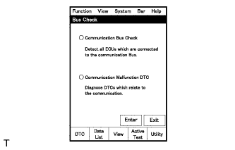
Select "Communication Malfunction DTC" from the "Bus Check" screen, and then select "Enter".
-
Select the system of the DTC to be checked and select "Details".
-
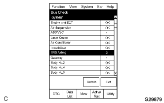
CAN communication system DTC(s) is/are displayed.
-
-
BUS CHECK (COMMUNICATION BUS CHECK)
Tech Tips
The ECUs and sensors that are properly connected to the CAN communication system can be displayed using the intelligent tester.
-
Select "Communication Bus Check" from the "Bus Check" screen.
-
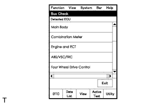
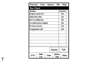
The screen displays the ECUs and sensors that are properly connected to the CAN communication system.
Tech Tips
If any properly connected ECUs or sensors are not displayed, there is a communication stop in the system.
-
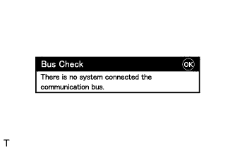
"There is no system connected to the communication bus" is displayed if there are no ECUs or sensors connected to the CAN bus.
-
-
DTC TABLE BY ECU
Tech Tips
-
In the CAN communication system, CAN communication system DTCs can be displayed by the ECU using the intelligent tester.
-
If CAN communication system DTCs are output, troubleshooting cannot be determined only by the DTCs. Perform troubleshooting according to How to Proceed with Troubleshooting Click here.
-
ECM / Intelligent Tester Display "Engine"
Tech Tips
DTC communication uses the CAN communication system.
DTC Code Detection Item U0101*1 Lost Communication with TCM U0129*2 Lost Communication with Skid Control ECU -
TCM / Intelligent Tester Display "ECT"
Tech Tips
DTC communication uses the CAN communication system.
DTC Code Detection Item U0100 Lost Communication with ECM / PCM "A" Tech Tips
Refer to Automatic Transaxle system Click here
-
Main Body ECU / Intelligent Tester Display "Main Body"
Tech Tips
DTC communication uses the CAN communication system.
DTC Code Detection Item U0199 Lost Communication with "Door Control Module A" U0201 Lost Communication with "Door Control Module C" U0202 Lost Communication with "Door Control Module D" U0208 Lost Communication with "Seat Control Module A" U0230 Lost Communication with Rear Gate Module U0327 Software Incompatibility with Vehicle Security Control Module U1002 Lost Communication with Gateway Module (Main body ECU) U1110 Lost Communication with Clearance Sonar Module -
Combination Meter / Intelligent Tester Display "Combination Meter"
Tech Tips
DTC communication uses the CAN communication system.
DTC Code Detection Item U0100 Lost Communication with ECM / PCM "A" U0129 Lost Communication with Skid Control ECU -
Power Steering ECU / Intelligent Tester Display "EPS"
Tech Tips
DTC communication uses the CAN communication system.
DTC Code Detection Item U0100 Lost Communication with ECM / PCM "A" U0129 Lost Communication with Brake System Control Module -
Air Conditioning Amplifier / Intelligent Tester Display "Air Conditioner"
Tech Tips
-
DTC communication uses the CAN communication system.
-
DTCs can be checked using the air conditioning control assembly (DTC 99 is output).
DTC Code Detection Item U0100 Lost Communication with ECM U0131 Lost Communication with Electric Power Steering ECU U0142 Lost Communication with Main Body ECU U0155 Lost Communication with Combination Meter -
-
Center Airbag Sensor Assembly / Intelligent Tester Display "SRS Airbag"
Tech Tips
The center airbag sensor assembly is connected to the CAN communication system, but CAN communication DTCs are not output.
-
Brake Actuator (Skid control ECU) / Intelligent Tester Display "ABS/VSC/TRC"
Tech Tips
DTC communication uses the CAN communication system.
DTC Code Detection Item U0073 Control Module Communication Bus OFF U0100 Lost Communication with ECM / PCM U0123 Lost Communication with Yaw Rate Sensor Module U0124 Lost Communication with Lateral Acceleration Sensor Module U0126 Lost Communication with Steering Angle Sensor Module -
Steering Angle Sensor / Intelligent Tester Display "Steering Angle Sensor"
Tech Tips
The steering angle sensor is connected to the CAN communication system, but CAN communication DTCs are not output.
-
Yaw Rate and Acceleration Sensor / Intelligent Tester Display "Yaw Rate / Deceleration Sensor"
Tech Tips
The yaw rate and acceleration sensor is connected to the CAN communication system, but CAN communication DTCs are not output.
-
Certification ECU (Smart Key ECU Assembly) / Intelligent Tester Display "Entry & Start / Wireless Tuner"
Tech Tips
The certification ECU (smart key ECU assembly) is connected to the CAN communication system, but CAN communication DTCs are not output.
-
Slide Door Motor Unit LH (Power Slide Door ECU LH) / Intelligent Tester Display "Rear Left Door"
Tech Tips
The slide door motor unit LH (power slide door ECU LH) is connected to the CAN communication system, but CAN communication DTCs are not output.
-
Slide Door Motor Unit RH (Power Slide Door ECU RH) / Intelligent Tester Display "Rear Right Door"
Tech Tips
The slide door motor unit RH (power slide door ECU RH) is connected to the CAN communication system, but CAN communication DTCs are not output.
-
Back Door Motor Unit (Power Back Door ECU) / Intelligent Tester Display "Power Back Door"
Tech Tips
The back door motor unit (power back door ECU) is connected to the CAN communication system, but CAN communication DTCs are not output.
-
Multiplex Network Door ECU (Back Door Closer ECU) / Intelligent Tester Display "Back Door"
Tech Tips
The multiplex network door ECU (Back Door Closer ECU) is connected to the CAN communication system, but CAN communication DTCs are not output.
-
Clearance Warning ECU / Intelligent Tester Display "Clearance Sonar"
Tech Tips
DTC communication uses the CAN communication system.
DTC Code Detection Item U0101 Lost Communication with ECM U0142 Lost Communication with Main Body ECU U0155 Lost Communication with Instrument Panel Cluster Control Module (Combination Meter) -
Outer Mirror Control ECU / Intelligent Tester Display "Drive Door/Mirror"
Tech Tips
The outer mirror control ECU is connected to the CAN communication system, but CAN communication DTCs are not output.
-
Position Control ECU and Switch (Position Control ECU) / Intelligent Tester Display "Drive Seat"
Tech Tips
The position control ECU and switch (position control ECU) is connected to the CAN communication system, but CAN communication DTCs are not output.
-
AFS ECU / Intelligent Tester Display "AFS/HL AutoLeveling"
Tech Tips
DTC communication uses the CAN communication system.
DTC Code Detection Item B2427 CAN Communication Malfunction -
Navigation ECU Sub-Assembly / Intelligent tester display "AVN1" (for LHD)
Tech Tips
DTC communication uses the CAN communication system.
DTC Code Detection Item U0073 Sending Malfunction (Navigation to APGS) U0100 Lost Communication with ECM U0126 Steering Sensor Communication U0140 Lost Communication with Body Control Module U0110 Lost Communication with Clearance Warning ECU
-
-
DTC COMBINATION TABLE
-
CAN No. 1 Bus
DTC Trouble Mode Output ECU Output DTC Main Body ECU Communication Stop Mode Combination Meter ECU Communication Stop Mode Air Conditioning Amplifier Communication Stop Mode Center Airbag Sensor Communication Stop Mode ECM Communication Stop Mode ECM U0129 X X X X ○*1 Combination meter U0100 X ○*1 X X ○ U0129 X ○*1 X X X Air conditioning amplifier (99) X ○*2 ○*3 X ○*2 U0100 X X ○*3 X ○ U0131 X X ○*3 X X U0142 ○ X ○*3 X X U0155 X ○ ○*3 X X Skid control ECU U0073 X X X X X U0100 X X X X ○ U0123 X X X X X U0124 X X X X X U0126 X X X X X Power steering ECU U0100 X X X X ○ U0129 X X X X X AFS ECU B2427 ○ ○ X X ○ Navigation ECU*5 U0073 X X X X X DTC Trouble Mode Output ECU Output DTC Skid Control ECU Communication Stop Mode Yaw Rate Sensor Communication Stop Mode Steering Angle Sensor Communication Stop Mode Power Steering ECU Communication Stop Mode Navigation ECU Communication Stop Mode*5 AFS ECU Communication Stop Mode ECM U0129 ○ X X X X X Combination meter U0100 X X X X X X U0129 ○ X X X X X Air conditioning amplifier (99) X X X X X X U0100 X X X X X X U0131 X X X ○ X X U0142 X X X X X X U0155 X X X X X X Skid control ECU U0073 ○*1, 4 X X X X X U0100 ○*1 X X X X X U0123 ○*1 ○ X X X X U0124 ○*1 ○ X X X X U0126 ○*1 X ○ X X X Power steering ECU U0100 X X X ○*1 X X U0129 ○ X X ○*1 X X AFS ECU B2427 ○ X ○ X X ○*1 Navigation ECU*5 U0073 X X X X ○*1 X Tech Tips
-
○: Set
-
X: Not set or may be set according to the malfunctioning part when one side of the CAN branch wire opens.
-
*1: DTC is not output during communication error, but will be output as a history DTC (past DTC) when communication returns to normal.
-
*2: DTC is stored only if communication between the air conditioning amplifier and both ECU is simultaneously interrupted.
-
*3: DTC is not output during communication error.
-
*4: DTC U0100, U0123, U0124 and U0126 are not stored when DTC U0073 has already been stored.
-
*5: for LHD only
-
Skid Control ECU Communication Stop Mode Click here
-
Air Conditioning Amplifier Communication Stop Mode Click here
-
Power Steering ECU Communication Stop Mode Click here
-
Steering Angle Sensor Communication Stop Mode Click here
-
Yaw Rate Sensor Communication Stop Mode Click here
-
ECM Communication Stop Mode Click here
-
Main Body ECU Communication Stop Mode Click here
-
Combination Meter ECU Communication Stop Mode Click here
-
Center Airbag Sensor Communication Stop Mode Click here
-
AFS ECU Communication Stop Mode Click here
-
Navigation ECU Communication Stop Mode (for LHD) Click here
-
-