CAN COMMUNICATION SYSTEM TERMINALS OF ECU

Note
-
Turn the engine switch off before measuring the resistances of CAN bus main wires and CAN bus branch wires.
-
After the engine switch is turned off, check that the key reminder warning system and light reminder warning system are not operating.
-
Before measuring the resistance, leave the vehicle as is for at least 1 minute and do not operate the engine switch, any other switches or doors. If any doors need to be opened in order to check the connectors, open the doors and leave them open.
Tech Tips
-
Operating the engine switch, any other switches or a door triggers related ECU and sensor communication on the CAN.
This communication will cause the resistance value to change.
-
Systems (ECUs and sensors) that adopt CAN communication vary depending on the options that the vehicle is equipped with. Check which systems (ECUs and sensors) are installed on the vehicle Click here.
Note
This section describes the standard values for all CAN related components.
-
CAN NO. 1 JUNCTION CONNECTOR RH (for RHD)
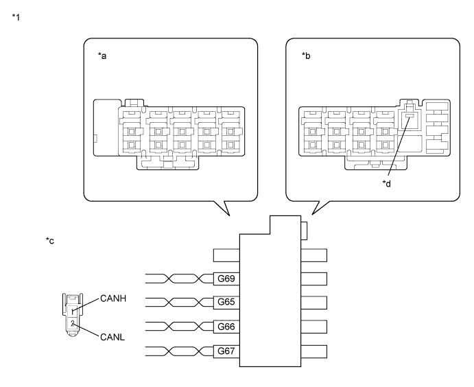
Text in Illustration *1 CAN No. 1 Junction Connector RH - - *a Junction Connector B Side *b Junction Connector A Side *c Front view of wire harness connector
(to CAN No. 1 Junction Connector RH)
*d Earth Terminal
-
Check the connection diagram of the components which are connected to the CAN No. 1 junction connector RH.
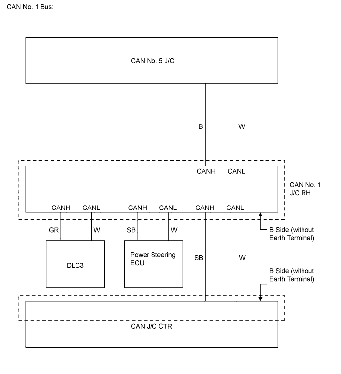
for CAN Junction Connector B Side Terminal No. (Symbol) Wiring Color Connected to G65-1 (CANH) SB Power steering ECU G65-2 (CANL) W G66-1 (CANH) GR DLC3 G66-2 (CANL) W G67-1 (CANH) SB CAN junction connector CTR G67-2 (CANL) W G69-1 (CANH) B CAN No. 5 junction connector G69-2 (CANL) W
-
-
CAN NO. 1 JUNCTION CONNECTOR RH (for LHD)

Text in Illustration *1 CAN No. 1 Junction Connector RH - - *a Junction Connector B Side *b Junction Connector A Side *c Front view of wire harness connector
(to CAN No. 1 Junction Connector RH)
*d Earth Terminal
-
Check the connection diagram of the components which are connected to the CAN No. 1 junction connector RH.
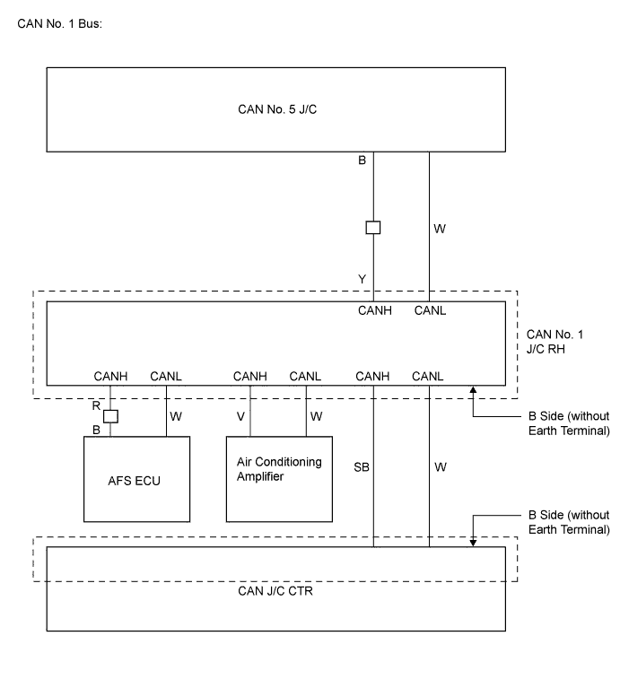
CAN Junction Connector B Side Terminal No. (Symbol) Wiring Color Connected to G67-1 (CANH) SB CAN junction connector CTR G67-2 (CANL) W G87-1 (CANH) R AFS ECU G87-2 (CANL) W G88-1 (CANH) Y CAN No. 5 junction connector G88-2 (CANL) W G89-1 (CANH) V Air conditioning amplifier G89-2 (CANL) W
-
-
CAN NO. 2 JUNCTION CONNECTOR RH (for RHD)

Text in Illustration *1 CAN No. 2 Junction Connector RH - - *a Junction Connector B Side *b Junction Connector A Side *c Front view of wire harness connector
(to CAN No. 2 Junction Connector RH)
*d Earth Terminal
-
Check the connection diagram of the components which are connected to the CAN No. 2 junction connector RH.
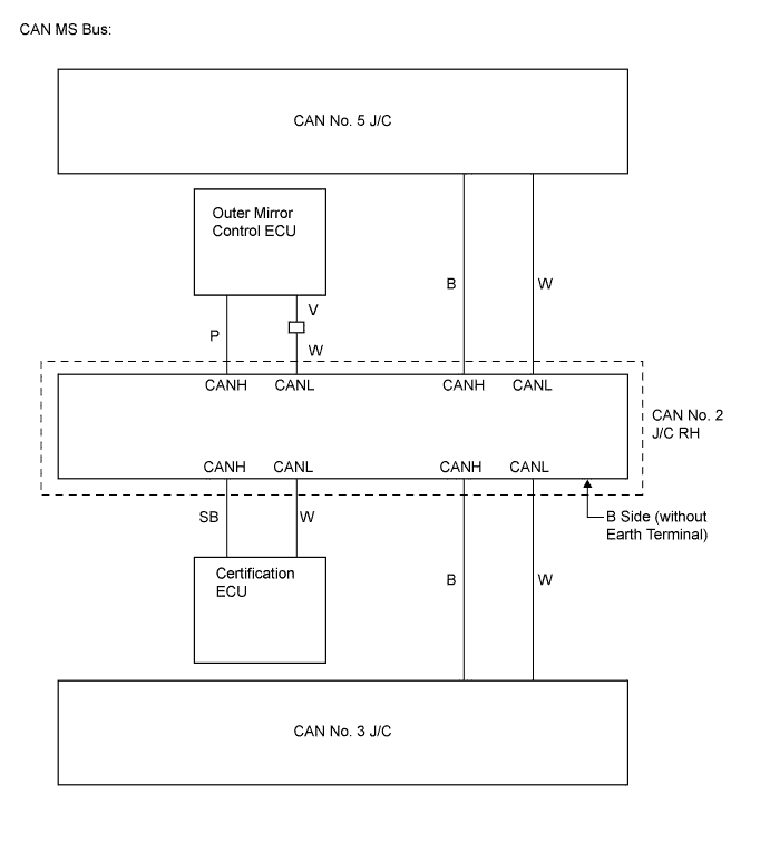
CAN Junction Connector B Side Terminal No. (Symbol) Wiring Color Connected to G70-1 (CANH) SB Certification ECU (Smart key ECU assembly) G70-2 (CANL) W G71-1 (CANH) B CAN No. 3 junction connector G71-2 (CANL) W G72-1 (CANH) B CAN No. 5 junction connector G72-2 (CANL) W G73-1 (CANH) P Outer mirror control ECU G73-2 (CANL) W
-
-
CAN NO. 2 JUNCTION CONNECTOR RH (for LHD)
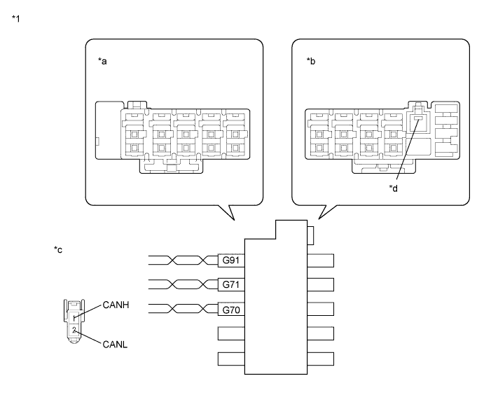
Text in Illustration *1 CAN No. 2 Junction Connector RH - - *a Junction Connector B Side *b Junction Connector A Side *c Front view of wire harness connector
(to CAN No. 2 Junction Connector RH)
*d Earth Terminal
-
Check the connection diagram of the components which are connected to the CAN No. 2 junction connector RH.
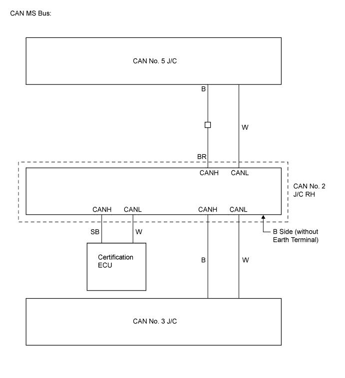
CAN Junction Connector B Side Terminal No. (Symbol) Wiring Color Connected to G70-1 (CANH) SB Certification ECU (Smart key ECU assembly) G70-2 (CANL) W G71-1 (CANH) B CAN No. 3 junction connector G71-2 (CANL) W G91-1 (CANH) BR CAN No. 5 junction connector G91-2 (CANL) W
-
-
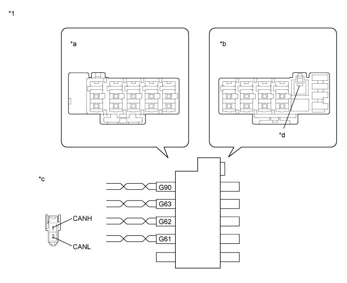
CAN JUNCTION CONNECTOR CTR (for RHD)
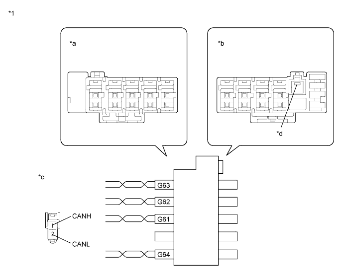
Text in Illustration *1 CAN Junction Connector CTR - - *a Junction Connector B Side *b Junction Connector A Side *c Front view of wire harness connector
(to CAN Junction Connector CTR)
*d Earth Terminal
-
Check the connection diagram of the components which are connected to the CAN junction connector CTR.
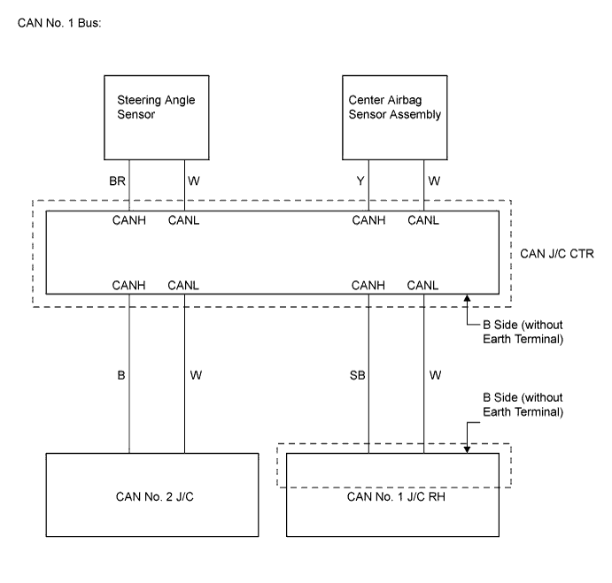
CAN Junction Connector B Side Terminal No. (Symbol) Wiring Color Connected to G61-1 (CANH) B CAN No. 2 junction connector G61-2 (CANL) W G62-1 (CANH) SB CAN No. 1 junction connector RH G62-2 (CANL) W G63-1 (CANH) Y Center airbag sensor assembly G63-2 (CANL) W G64-1 (CANH) BR Steering angle sensor G64-2 (CANL) W
-
-
CAN JUNCTION CONNECTOR CTR (for LHD)
Text in Illustration *1 CAN Junction Connector CTR - - *a Junction Connector B Side *b Junction Connector A Side *c Front view of wire harness connector
(to CAN Junction Connector CTR)
*d Earth Terminal
-
Check the connection diagram of the components which are connected to the CAN junction connector CTR.

CAN Junction Connector B Side Terminal No. (Symbol) Wiring Color Connected to G61-1 (CANH) R CAN No. 3 junction connector G61-2 (CANL) W G62-1 (CANH) SB CAN No. 1 junction connector RH G62-2 (CANL) W G63-1 (CANH) Y Center airbag sensor assembly G63-2 (CANL) W G90-1 (CANH) BR Steering angle sensor G90-2 (CANL) W
-
-
CAN NO. 2 JUNCTION CONNECTOR (for RHD)
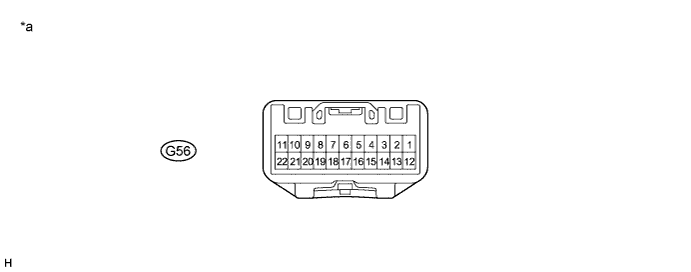
Text in Illustration *a Component without harness connected
(CAN No. 2 Junction Connector)
- -
-
Check the CAN No. 2 junction connector.
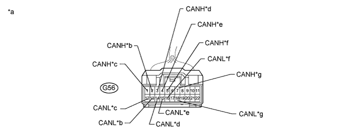
Text in Illustration *a Front view of wire harness connector
(to CAN No. 2 Junction Connector)
*b to Skid Control ECU *c to ECM *d to Main Body ECU *e to A/C Amplifier *f to CAN J/C CTR *g to AFS ECU - - -
Check the connection diagram of the components which are connected to the CAN No. 2 junction connector Click here.
Terminal No. (Symbol) Wiring Color Connected to G56-1 (CANH) B ECM G56-12 (CANL) W G56-2 (CANH) B Brake actuator (Skid control ECU) G56-13 (CANL) W G56-3 (CANH) G Main body ECU G56-14 (CANL) W G56-4 (CANH) V Air conditioning amplifier G56-15 (CANL) W G56-5 (CANH) B CAN junction connector CTR G56-16 (CANL) W G56-7 (CANH) GR AFS ECU G56-18 (CANL) W
-
-
CAN NO. 2 JUNCTION CONNECTOR (for LHD)
Text in Illustration *a Component without harness connected
(CAN No. 2 Junction Connector)
- -
-
Check the CAN No. 2 junction connector.
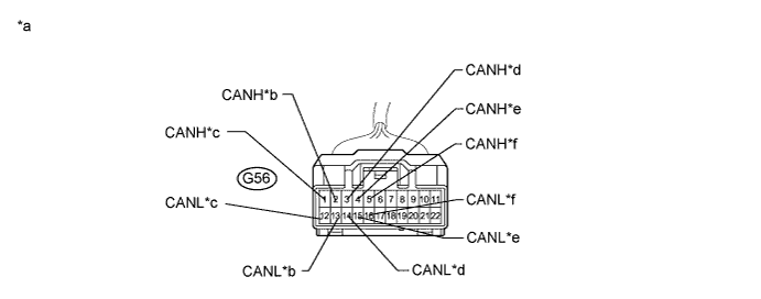
Text in Illustration *a Front view of wire harness connector
(to CAN No. 2 Junction Connector)
*b DLC3 *c to CAN No. 6 Junction Connector *d to Main Body ECU *e to Power Steering ECU *f to CAN No. 3 Junction Connector -
Check the connection diagram of the components which are connected to the CAN No. 2 junction connector Click here.
Terminal No. (Symbol) Wiring Color Connected to G56-1 (CANH) B CAN No. 6 junction connector G56-12 (CANL) W G56-2 (CANH) GR DLC3 G56-13 (CANL) W G56-3 (CANH) G Main body ECU G56-14 (CANL) W G56-4 (CANH) B Power steering ECU G56-15 (CANL) W G56-5 (CANH) B CAN No. 3 junction connector G56-16 (CANL) W
-
-
CAN NO. 3 JUNCTION CONNECTOR (for RHD)
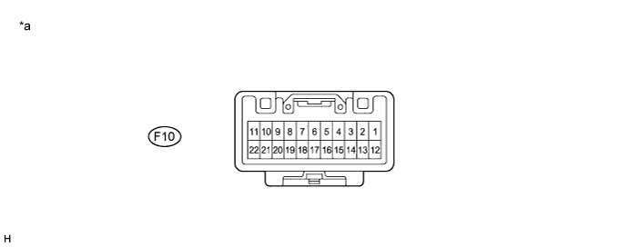
Text in Illustration *a Component without harness connected
(CAN No. 3 Junction Connector)
- -
-
Check the CAN No. 3 junction connector.
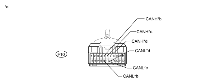
Text in Illustration *a Front view of wire harness connector
(to CAN No. 3 Junction Connector)
*b to CAN No. 2 J/C RH *c to CAN No. 4 J/C *d to Clearance Warning ECU -
Check the connection diagram of the components which are connected to the CAN No. 3 junction connector Click here.
Terminal No. (Symbol) Wiring Color Connected to F10-5 (CANH) B CAN No. 2 junction connector RH F10-16 (CANL) W F10-6 (CANH) B CAN No. 4 junction connector F10-17 (CANL) W F10-7 (CANH) B Clearance warning ECU F10-18 (CANL) W
-
-
CAN NO. 3 JUNCTION CONNECTOR (for LHD)
Text in Illustration *a Component without harness connected
(CAN No. 3 Junction Connector)
- -
-
Check the CAN No. 3 junction connector.
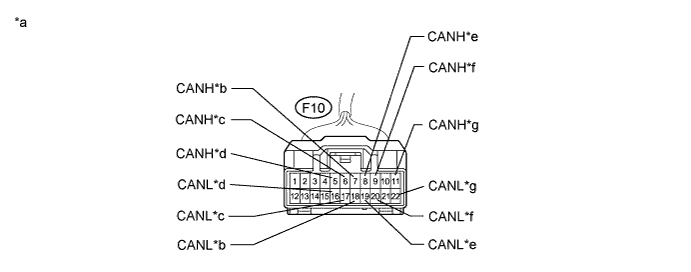
Text in Illustration *a Front view of wire harness connector
(to CAN No. 3 Junction Connector)
*b to Clearance Warning ECU *c to CAN No. 4 J/C *d to CAN No. 2 J/C RH *e to CAN J/C CTR *f to CAN No. 2 J/C *g to Navigation ECU - - -
Check the connection diagram of the components which are connected to the CAN No. 3 junction connector Click here.
Terminal No. (Symbol) Wiring Color Connected to F10-5 (CANH) B CAN No. 2 junction connector RH F10-16 (CANL) W F10-6 (CANH) B CAN No. 4 junction connector F10-17 (CANL) W F10-7 (CANH) B Clearance warning ECU F10-18 (CANL) W F10-8 (CANH) R CAN junction connector CTR F10-19 (CANL) W F10-9 (CANH) R CAN No. 2 junction connector F10-20 (CANL) W F10-11 (CANH) B Navigation ECU*1 F10-22 (CANL) W Tech Tips
*1: w/ Navigation system
-
-
CAN NO. 4 JUNCTION CONNECTOR (for RHD)

Text in Illustration *a Component without harness connected
(CAN No. 4 Junction Connector)
- -
-
Check the CAN No. 4 junction connector.
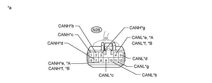
Text in Illustration *A w/ Power Back Door System *B w/o Power Back Door System *a Front view of wire harness connector
(to CAN No. 4 Junction Connector)
*b to CAN No. 3 J/C *c to Main Body ECU *d to Power Slide Door ECU LH *e to Power Back Door ECU *f to Back Door Closer ECU -
Check the connection diagram of the components which are connected to the CAN No. 4 junction connector Click here.
Terminal No. (Symbol) Wiring Color Connected to N28-1 (CANH) B Main body ECU N28-9 (CANL) W N28-2 (CANH) B CAN No. 3 junction connector N28-10 (CANL) W N28-3 (CANH) B Slide door motor unit LH (Power slide door ECU LH) N28-11 (CANL) W N28-8 (CANH) B Back door motor unit (Power back door ECU)*1 N28-4 (CANL) W N28-8 (CANH) B Multiplex network door ECU (Back door closer ECU)*2 N28-4 (CANL) W Tech Tips
-
*1: w/ Power back door system
-
*2: w/o Power back door system
-
-
-
CAN NO. 4 JUNCTION CONNECTOR (for LHD)
Text in Illustration *a Component without harness connected
(CAN No. 4 Junction Connector)
- -
-
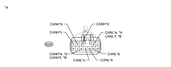
Check the CAN No. 4 junction connector.
Text in Illustration *A w/ Power Back Door System *B w/o Power Back Door System *a Front view of wire harness connector
(to CAN No. 4 Junction Connector)
*b to CAN No. 3 J/C *c to CAN No. 7 J/C *d to Position Control ECU *e to Power Back Door ECU *f to Back Door Closer ECU *g to Power Slide Door ECU LH - - -
Check the connection diagram of the components which are connected to the CAN No. 4 junction connector Click here.
Terminal No. (Symbol) Wiring Color Connected to N28-1 (CANH) B CAN No. 7 junction connector N28-9 (CANL) W N28-2 (CANH) B CAN No. 3 junction connector N28-10 (CANL) W N28-3 (CANH) B Slide door motor unit LH (Power slide door ECU LH) N28-11 (CANL) W N28-8 (CANH) B Back door motor unit (Power back door ECU)*1 N28-4 (CANL) W N28-8 (CANH) B Multiplex network door ECU (Back door closer ECU)*2 N28-4 (CANL) W N28-7 (CANH) GR Position control ECU and switch (Position control ECU) N28-5 (CANL) W Tech Tips
-
*1: w/ Power back door system
-
*2: w/o Power back door system
-
-
-
CAN NO. 5 JUNCTION CONNECTOR (for RHD)
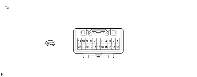
Text in Illustration *a Component without harness connected
(CAN No. 5 Junction Connector)
- -
-
Check the CAN No. 5 junction connector.
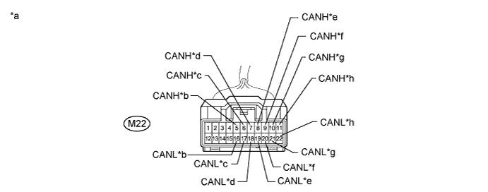
Text in Illustration *a Front view of wire harness connector
(to CAN No. 5 Junction Connector)
*b to Yaw Rate and Acceleration Sensor *c to CAN No. 1 J/C RH *d to Combination Meter *e to Position Control ECU *f to Power Slide Door ECU RH *g to Combination Meter *h to CAN No. 2 J/C RH -
Check the connection diagram of the components which are connected to the CAN No. 5 junction connector Click here.
Terminal No. (Symbol) Wiring Color Connected to M22-6 (CANH) B CAN No. 1 junction connector RH M22-17 (CANL) W M22-5 (CANH) B Yaw rate and acceleration sensor M22-16 (CANL) W M22-7 (CANH) B Combination meter M22-18 (CANL) W M22-8 (CANH) GR Position control ECU and switch (Position control ECU)*1 M22-19 (CANL) W M22-10 (CANH) B Combination meter M22-21 (CANL) W M22-11 (CANH) B CAN No. 2 junction connector RH M22-22 (CANL) W M22-9 (CANH) R Slide door motor unit RH (Power slide door ECU RH)*2 M22-20 (CANL) W Tech Tips
-
*1: w/ Seat position memory
-
*2: w/ Power slide door RH
-
-
-
CAN NO. 5 JUNCTION CONNECTOR (for LHD)
Text in Illustration *a Component without harness connected
(CAN No. 5 Junction Connector)
- -
-
Check the CAN No. 5 junction connector.
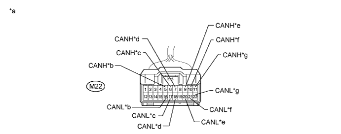
Text in Illustration *a Front view of wire harness connector
(to CAN No. 5 Junction Connector)
*b to Yaw Rate and Acceleration Sensor *c to CAN No. 1 J/C RH *d to Combination Meter *e to Power Slide Door ECU RH *f to Combination Meter *g to CAN No. 2 J/C RH - - -
Check the connection diagram of the components which are connected to the CAN No. 5 junction connector Click here.
Terminal No. (Symbol) Wiring Color Connected to M22-6 (CANH) B CAN No. 1 junction connector RH M22-17 (CANL) W M22-5 (CANH) B Yaw rate and acceleration sensor M22-16 (CANL) W M22-7 (CANH) B Combination meter M22-18 (CANL) W M22-10 (CANH) B Combination meter M22-21 (CANL) W M22-11 (CANH) B CAN No. 2 junction connector RH M22-22 (CANL) W M22-9 (CANH) R Slide door motor unit RH (Power slide door ECU RH) M22-20 (CANL) W
-
-
CAN NO. 6 JUNCTION CONNECTOR (for LHD)
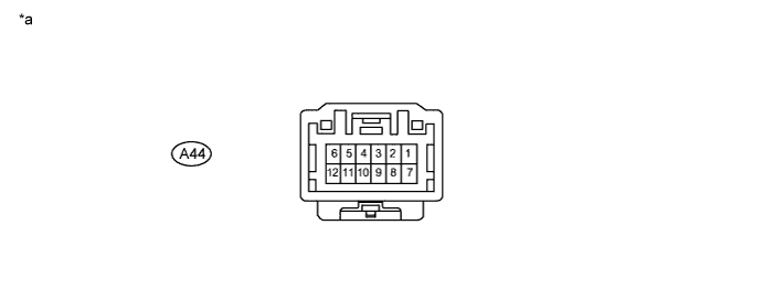
Text in Illustration *a Component without harness connected
(CAN No. 6 Junction Connector)
- -
-
Check the CAN No. 6 junction connector.
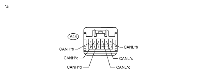
Text in Illustration *a Front view of wire harness connector
(to CAN No. 6 Junction Connector)
*b to ECM *c to Skid Control ECU *d to CAN No. 2 J/C -
Check the connection diagram of the components which are connected to the CAN No. 6 junction connector Click here.
Terminal No. (Symbol) Wiring Color Connected to A44-1 (CANH) L ECM A44-6 (CANL) Y A44-2 (CANH) V Brake actuator (Skid control ECU) A44-4 (CANL) P A44-3 (CANH) B CAN No. 2 junction connector A44-5 (CANL) W
-
-
CAN NO. 7 JUNCTION CONNECTOR (for LHD)
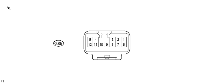
Text in Illustration *a Component without harness connected
(CAN No. 7 Junction Connector)
- -
-
Check the CAN No. 7 junction connector.
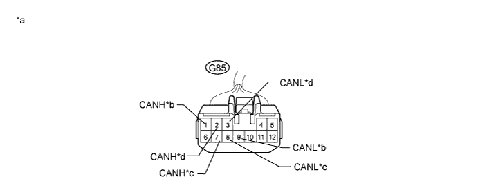
Text in Illustration *a Front view of wire harness connector
(to CAN No. 7 Junction Connector)
*b to CAN No. 4 J/C *c to Outer Mirror Control ECU *d to Main Body ECU -
Check the connection diagram of the components which are connected to the CAN No. 7 junction connector Click here.
Terminal No. (Symbol) Wiring Color Connected to G85-1 (CANH) B CAN No. 4 junction connector G85-9 (CANL) W G85-2 (CANH) B Main body ECU G85-3 (CANL) W G85-7 (CANH) P Outer mirror control ECU G85-8 (CANL) W
-
-
DLC3
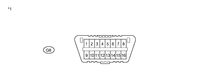
Terminal No. (Symbol) Terminal Description G8-4 (CG) Chassis ground G8-6 (CANH) HIGH-level CAN bus line G8-14 (CANL) LOW-level CAN bus line G8-16 (BAT) Battery positive Text in Illustration *1 DLC3 - -
-
Measure the resistance according to the value(s) in the table below.
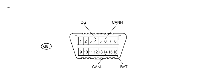
Text in Illustration *1 DLC3 - -
-
-
ECM
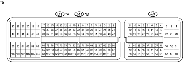
Terminal No. (Symbol) Terminal Description A8-20 (BATT) Power supply A8-41 (CANH) CAN communication line H A8-49 (CANL) CAN communication line L D1-81 (E1)*1
D41-104 (E1)*2
Ground Tech Tips
-
*1: for 2GR-FE
-
*2: for 2AZ-FE
Text in Illustration *A for 2GR-FE *B for 2AZ-FE *a Component without harness connected
(ECM)
- -
-
Disconnect the connectors of the ECM.
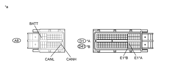
Text in Illustration *A for 2GR-FE *B for 2AZ-FE *a Front view of wire harness connector
(to ECM)
- - -
Measure the resistance according to the value(s) in the table below.
-
*1: for RHD
-
*2: for LHD
-
*3: for 2GR-FE
-
*4: for 2AZ-FE
-
-
-
MAIN BODY ECU
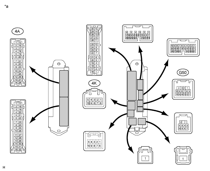
Terminal No. (Symbol) Terminal Description 4K-9 (BATB) Power supply G50-1 (GND) Ground G50-5 (CANH) CAN communication line H G50-6 (CANL) CAN communication line L G50-15 (CANN) CAN communication line L G50-16 (CANP) CAN communication line H Text in Illustration *a Component without harness connected
(Main Body ECU)
- -
-
Disconnect the connector of the main body ECU.
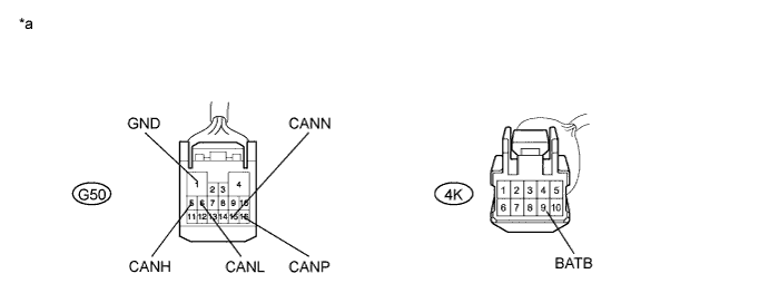
Text in Illustration *a Front view of wire harness connector
(to Main Body ECU)
- - -
Measure the resistance according to the value(s) in the table below.
-
-
COMBINATION METER
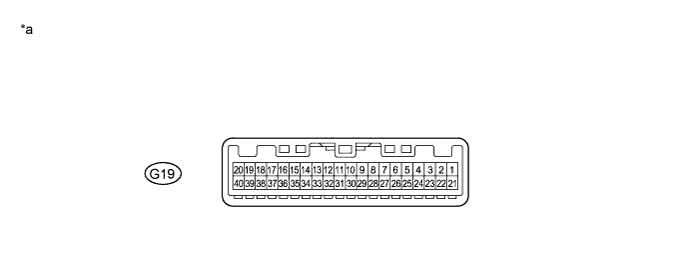
Terminal No. (Symbol) Terminal Description G19-2 (B) Power supply G19-3 (EP) Ground G19-13 (CANH) CAN communication line H G19-14 (CANL) CAN communication line L G19-25 (MPX-) CAN communication line L G19-26 (MPX+) CAN communication line H Text in Illustration *a Component without harness connected
(Combination Meter)
- -
-
Disconnect the connector of the combination meter.
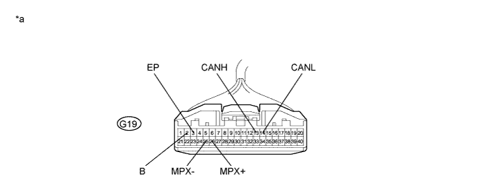
Text in Illustration *a Front view of wire harness connector
(to Combination Meter)
- - -
Measure the resistance according to the value(s) in the table below.
-
-
POWER STEERING ECU
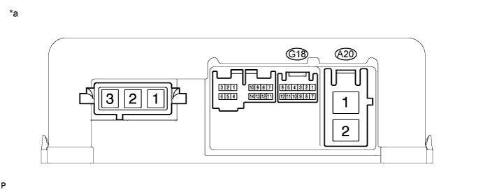
Terminal No. (Symbol) Terminal Description G18-1 (CANH) CAN communication line H G18-7 (CANL) CAN communication line L A20-1 (PIG) Power supply A20-2 (PGND) Ground Text in Illustration *a Component without harness connected
(Power Steering ECU)
- -
-
Disconnect the connectors of the power steering ECU.
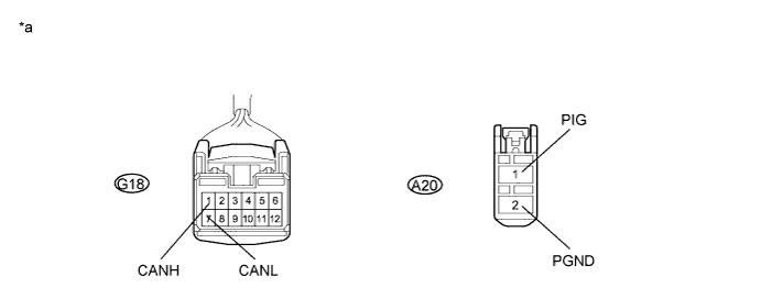
Text in Illustration *a Front view of wire harness connector
(to Power Steering ECU)
- - -
Measure the resistance according to the value(s) in the table below.
-
*1: for RHD
-
*2: for LHD
-
-
-
AIR CONDITIONING AMPLIFIER
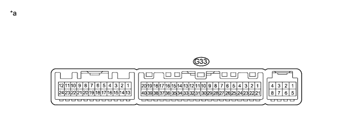
Terminal No. (Symbol) Terminal Description G33-11 (CANH) CAN communication line H G33-12 (CANL) CAN communication line L G33-14 (GND) Ground G33-21 (B) Power supply Text in Illustration *a Component without harness connected
(Air Conditioning Amplifier)
- -
-
Disconnect the connector of the air conditioning amplifier.
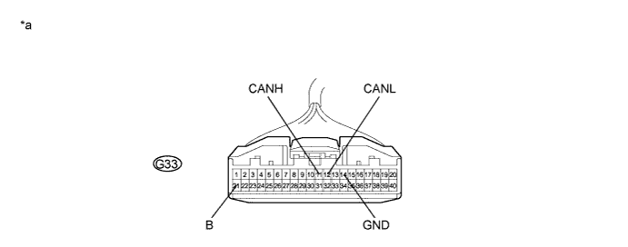
Text in Illustration *a Front view of wire harness connector
(to Air Conditioning Amplifier)
- - -
Measure the resistance according to the value(s) in the table below.
-
-
CENTER AIRBAG SENSOR ASSEMBLY
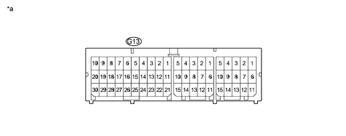
Terminal No. (Symbol) Terminal Description G13-13 (CANH) CAN communication line H G13-22 (CANL) CAN communication line L G13-25 (E1) Ground G13-26 (E2) Ground Text in Illustration *a Component without harness connected
(Center Airbag Sensor Assembly)
- -
-
Disconnect the connector of the center airbag sensor assembly.
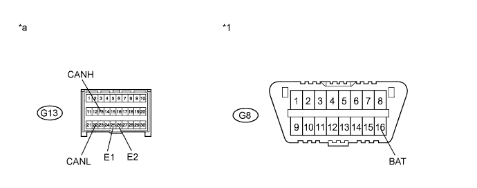
Text in Illustration *1 DLC3 - - *a Front view of wire harness connector
(to Center Airbag Sensor Assembly)
- - -
Measure the resistance according to the value(s) in the table below.
-
-
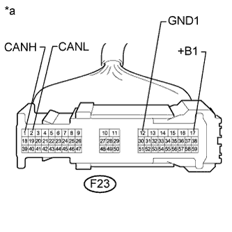
BRAKE ACTUATOR (SKID CONTROL ECU)
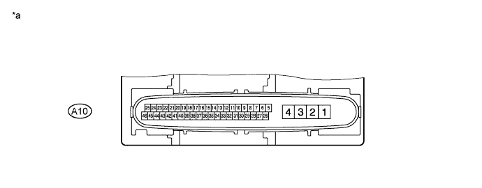
Terminal No. (Symbol) Terminal Description A10-3 (+BS) Power supply A10-4 (GND1) Ground A10-14 (CANL) CAN communication line L A10-35 (CANH) CAN communication line H Text in Illustration *a Component without harness connected
(Skid Control ECU)
- -
-
Disconnect the connector of the brake actuator (skid control ECU).
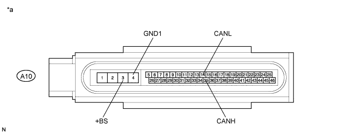
Text in Illustration *a Front view of wire harness connector
(to Skid Control ECU)
- - -
Measure the resistance according to the value(s) in the table below.
-
*1: for RHD
-
*2: for LHD
-
-
-
STEERING ANGLE SENSOR
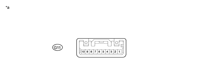
Terminal No. (Symbol) Terminal Description G11-2 (ESS) Ground G11-3 (BAT) Power supply G11-9 (CANL) CAN communication line L G11-10 (CANH) CAN communication line H Text in Illustration *a Component without harness connected
(Steering Angle Sensor)
- -
-
Disconnect the connector of the steering angle sensor.
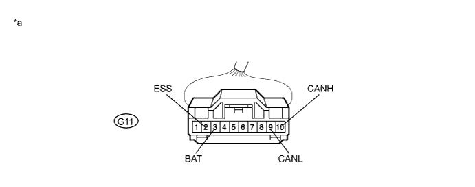
Text in Illustration *a Front view of wire harness connector
(to Steering Angle Sensor)
- - -
Measure the resistance according to the value(s) in the table below.
-
-
YAW RATE AND ACCELERATION SENSOR
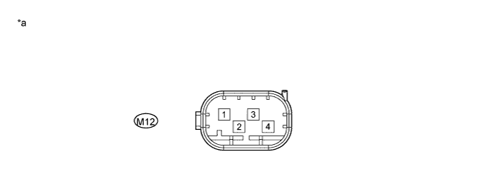
Terminal No. (Symbol) Terminal Description M12-4 (GNDA) Ground M12-3 (CANL) CAN communication line L M12-2 (CANH) CAN communication line H Text in Illustration *a Component without harness connected
(Yaw Rate and Acceleration Sensor)
- -
-
Disconnect the connector of the yaw rate and acceleration sensor.
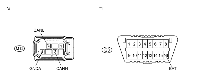
Text in Illustration *1 DLC3 - - *a Front view of wire harness connector
(to Yaw Rate and Acceleration Sensor)
- - -
Measure the resistance according to the value(s) in the table below.
-
-
CERTIFICATION ECU (SMART KEY ECU ASSEMBLY)
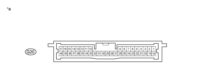
Terminal No. (Symbol) Terminal Description G20-1 (+B) Power supply G20-17 (E) Ground G20-27 (CANH) CAN communication line H G20-28 (CANL) CAN communication line L Text in Illustration *a Component without harness connected
(Certification ECU)
- -
-
Disconnect the connector of the certification ECU (smart key ECU assembly).
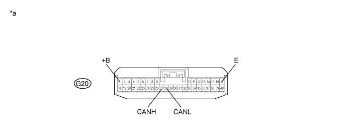
Text in Illustration *a Front view of wire harness connector
(to Certification ECU)
- - -
Measure the resistance according to the value(s) in the table below.
-
-
SLIDE DOOR MOTOR UNIT LH (POWER SLIDE DOOR ECU LH)
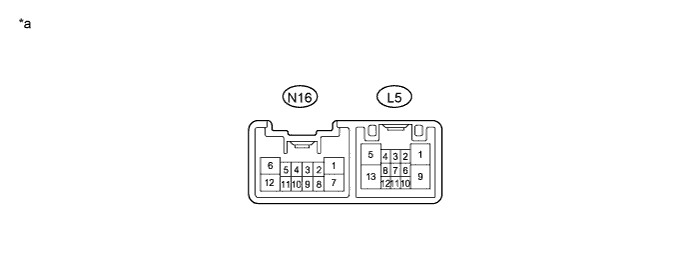
Terminal No. (Symbol) Terminal Description N16-1 (GND) Ground N16-5 (MPX2) CAN communication line L N16-11 (MPX1) CAN communication line H N16-12 (ECUB) Power supply Text in Illustration *a Component without harness connected
(Power Slide Door ECU LH)
- -
-
Disconnect the connector of the slide door motor unit LH (power slide door ECU LH).
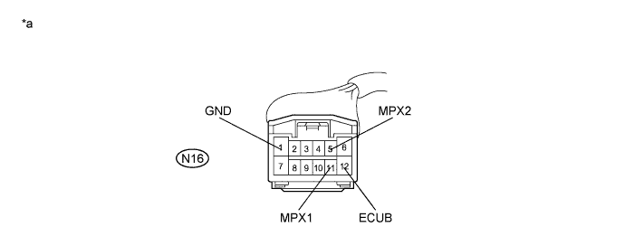
Text in Illustration *a Front view of wire harness connector
(to Power Slide Door ECU LH)
- - -
Measure the resistance according to the value(s) in the table below.
-
-
SLIDE DOOR MOTOR UNIT RH (POWER SLIDE DOOR ECU RH)
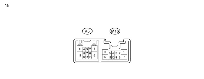
Terminal No. (Symbol) Terminal Description M16-2 (MPX2) CAN communication line L M16-6 (GND) Ground M16-7 (ECUB) Power supply M16-8 (MPX1) CAN communication line H Text in Illustration *a Component without harness connected
(Power Slide Door ECU RH)
- -
-
Disconnect the connector of the slide door motor unit RH (power slide door ECU RH).
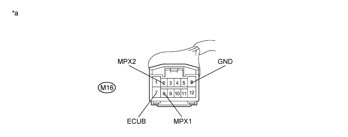
Text in Illustration *a Front view of wire harness connector
(to Power Slide Door ECU RH)
- - -
Measure the resistance according to the value(s) in the table below.
-
-
BACK DOOR MOTOR UNIT (POWER BACK DOOR ECU)
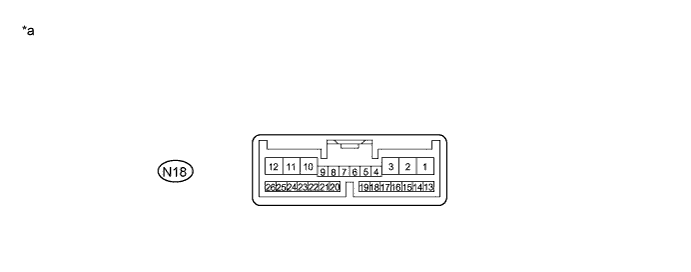
Terminal No. (Symbol) Terminal Description N18-5 (MPX2) CAN communication line L N18-6 (MPX1) CAN communication line H N18-10 (ECUB) Power supply N18-11 (GND) Ground Text in Illustration *a Component without harness connected
(Power Back Door ECU)
- -
-
Disconnect the connector of the back door motor unit (power back door ECU).
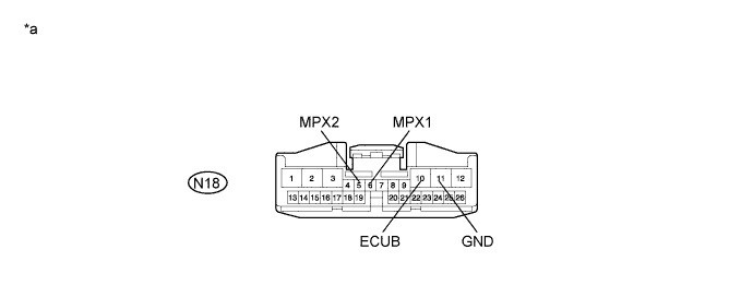
Text in Illustration *a Front view of wire harness connector
(to Power Back Door ECU)
- - -
Measure the resistance according to the value(s) in the table below.
-
-
MULTIPLEX NETWORK DOOR ECU (BACK DOOR CLOSER ECU)

Terminal No. (Symbol) Terminal Description N33-12 (MPX2) CAN communication line L N33-11(MPX1) CAN communication line H N33-16 (ECUB) Power supply N33-3 (GND) Ground Text in Illustration *a Component without harness connected
(Back Door Closer ECU)
- -
-
Disconnect the connector of the multiplex network door ECU (back door closer ECU).
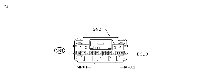
Text in Illustration *a Front view of wire harness connector
(to Back Door Closer ECU)
- - -
Measure the resistance according to the value(s) in the table below.
-
-
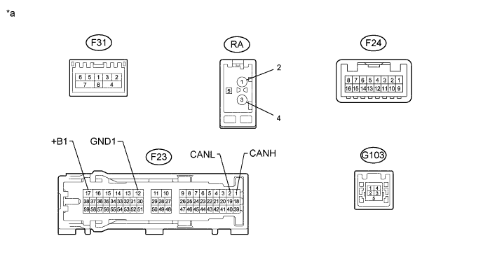
CLEARANCE WARNING ECU
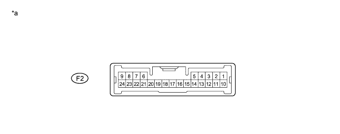
Terminal No. (Symbol) Terminal Description F2-19 (R1) CAN communication line H F2-20 (R2) CAN communication line L F2-21 (E) Ground Text in Illustration *a Component without harness connected
(Clearance Warning ECU)
- -
-
Disconnect the connector of the clearance warning ECU.

Text in Illustration *1 DLC3 - - *a Front view of wire harness connector
(to Clearance Warning ECU)
- - -
Measure the resistance according to the value(s) in the table below.
-
-
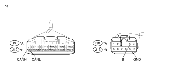
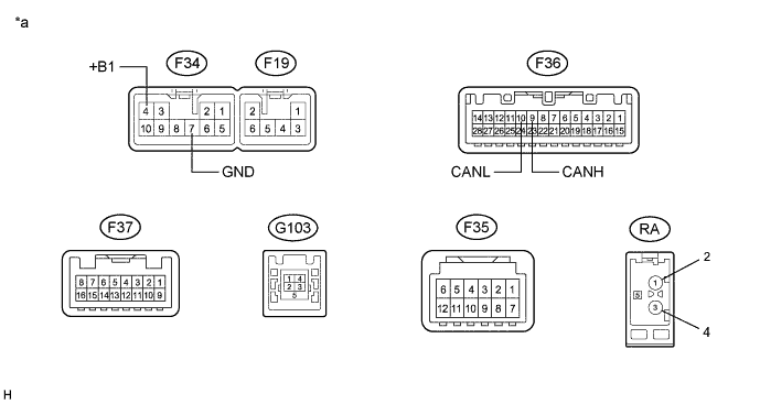
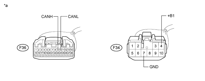
OUTER MIRROR CONTROL ECU
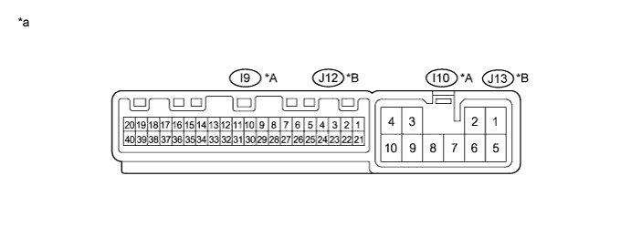
Terminal No. (Symbol) Terminal Description I9-1 (CANH)*1
J12-1 (CANH)*2
CAN communication line H I9-21 (CANL)*1
J12-21 (CANL)*2
CAN communication line L I10-3 (B)*1
J13-3 (B)*2
Power supply I10-9 (GND)*1
J13-9 (GND)*2
Ground
-
*1: for RHD
-
*2: for LHD
Text in Illustration *A for RHD *B for LHD *a Component without harness connected
(Outer Mirror Control ECU)
- -
-
Disconnect the connectors of the outer mirror control ECU.
Text in Illustration *A for RHD *B for LHD *a Front view of wire harness connector
(to Outer Mirror Control ECU)
- - -
Measure the resistance according to the value(s) in the table below.
-
*1: for RHD
-
*2: for LHD
-
-
-
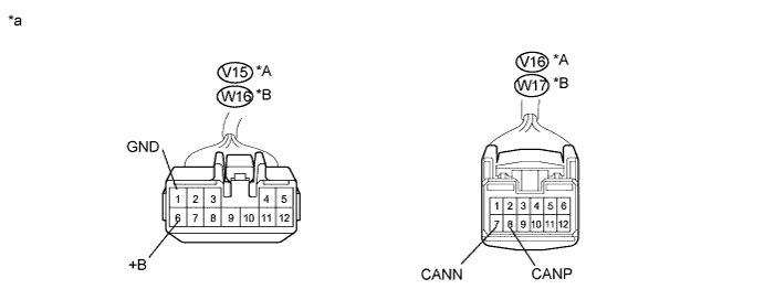
POSITION CONTROL ECU AND SWITCH (POSITION CONTROL ECU)

Terminal No. (Symbol) Terminal Description V16-7 (CANN)*1
W17-7 (CANN)*2
CAN communication line L V16-8 (CANP)*1
W17-8 (CANP)*2
CAN communication line H V15-1 (GND)*1
W16-1 (GND)*2
Ground V15-6 (+B)*1
W16-6 (+B)*2
Power supply Tech Tips
-
*1: for RHD
-
*2: for LHD
Text in Illustration *A for RHD *B for LHD *a Component without harness connected
(Position Control ECU)
- -
-
Disconnect the connectors of the position control ECU and switch (position control ECU).
Text in Illustration *A for RHD *B for LHD *a Front view of wire harness connector
(to Position Control ECU)
- - -
Measure the resistance according to the value(s) in the table below.
Tech Tips
-
*1: for RHD
-
*2: for LHD
-
-
-
AFS ECU
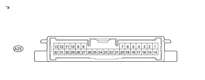
Terminal No. (Symbol) Terminal Description A23-12 (CANH) CAN communication line H A23-13 (CANL) CAN communication line L A23-22 (E1) Ground Text in Illustration *a Component without harness connected
(AFS ECU)
- -
-
Disconnect the connector of the AFS ECU.
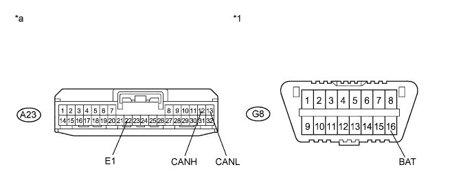
Text in Illustration *1 DLC3 - - *a Front view of wire harness connector
(to AFS ECU)
- - -
Measure the resistance according to the value(s) in the table below.
-
-
NAVIGATION ECU SUB-ASSEMBLY (w/ Front Center Speaker)
Text in Illustration *a Component without harness connected
(Navigation ECU Sub-Assembly)
- -
-
Text in Illustration *a Front view of wire harness connector
(to Navigation ECU Sub-Assembly)
Disconnect the connector from the navigation ECU sub-assembly.
-
Measure the resistance according to the value(s) in the table below.
-
-
NAVIGATION ECU SUB-ASSEMBLY (w/o Front Center Speaker)
Text in Illustration *a Component without harness connected
(Navigation ECU Sub-Assembly)
- -
-
Disconnect the connectors from the navigation ECU sub-assembly.
Text in Illustration *a Front view of wire harness connector
(to Navigation ECU Sub-Assembly)
- - -
Measure the resistance according to the value(s) in the table below.
-