DESCRIPTION
This DTC is output when LIN communication between the power window regulator motor assembly (for driver side) and main body ECU stops for more than 10 seconds.
| DTC Code | DTC Detection Condition | Trouble Area |
|---|---|---|
| B2321 | No communication between front power window regulator motor assembly (for driver side) and main body ECU for more than 10 seconds. |
|
-
*1: for LHD
-
*2: for RHD
INSPECTION PROCEDURE
-
When the power window regulator motor assembly (for driver side) is replaced or removed and reinstalled, it requires initialization (Click here).
-
When using the intelligent tester to troubleshoot with the engine switch off:
Connect the intelligent tester to the DLC3, and turn the courtesy switch on and off at 1.5-second intervals until communication between the tester and vehicle begins.
PROCEDURE
- Click here
CHECK DTC OUTPUT
-
Clear the DTC (Click here).
-
Recheck for DTCs.
Result Result Proceed to Only DTC B2321 is output. A DTC B1206 and B2321 are output simultaneously. B Tip:When DTC B1206 and B2321 are output simultaneously, perform troubleshooting for DTC B1206 first.
-
- Click here
CHECK HARNESS AND CONNECTOR (POWER WINDOW REGULATOR MOTOR - BATTERY AND BODY GROUND)
-
Disconnect the J4*1 or I4*2 motor connector.
-
*1: for LHD
-
*2: for RHD
-
-
Measure the resistance and voltage according to the value(s) in the table below.
Standard Resistance Table 1. for LHD Tester Connection Condition Specified Condition J4-1 (GND) - Body ground Always Below 1 Ω Table 2. for RHD Tester Connection Condition Specified Condition I4-1 (GND) - Body ground Always Below 1 Ω Standard Voltage Table 3. for LHD Tester Connection Condition Specified Condition J4-2 (B) - Body ground Always 11 to 14 V Table 4. for RHD Tester Connection Condition Specified Condition I4-2 (B) - Body ground Always 11 to 14 V
- OKClick here
- NGClick here
-
- Click here
CHECK HARNESS AND CONNECTOR (MASTER SWITCH - POWER WINDOW REGULATOR MOTOR ASSEMBLY)
-
Disconnect the J10*1 or I3*2 switch connector.
-
*1: for LHD
-
*2: for RHD
-
-
Measure the resistance according to the value(s) in the table below.
Standard Resistance Table 5. for LHD Tester Connection Condition Specified Condition J10-16 (LIN2) - J4-9 (LIN) Always Below 1 Ω J10-16 (LIN2) - Body ground Always 10 kΩ or higher Table 6. for RHD Tester Connection Condition Specified Condition I3-16 (LIN2) - I4-9 (LIN) Always Below 1 Ω I3-16 (LIN2) - Body ground Always 10 kΩ or higher
- OKClick here
- NGClick here
-
- Click here
INSPECT MULTIPLEX NETWORK MASTER SWITCH ASSEMBLY
-
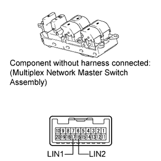
Remove the multiplex network master switch assembly (Click here).
-
Measure the resistance according to the value(s) in the table below.
Standard Resistance Tester Connection Condition Specified Condition 16 (LIN2) - 17 (LIN1) Always Below 1 Ω
- OKClick here
- NGClick here
-
- Click here
REPLACE POWER WINDOW REGULATOR MOTOR ASSEMBLY (for DRIVER SIDE)
-
Replace the power window regulator motor assembly (for driver side) (Click here).
- NEXTClick here
-
- Click here
CHECK DTC OUTPUT
-
Clear the DTC (Click here).
-
Recheck for DTCs.
OK DTC B2321 is not output.
- OKClick here
- NGClick here
-
- Click here
REPAIR OR REPLACE HARNESS OR CONNECTOR
- Click here
REPAIR OR REPLACE HARNESS OR CONNECTOR, OR REPLACE FUSE
- Click here
REPLACE MAIN BODY ECUClick here
- Click here
END (POWER WINDOW REGULATOR MOTOR ASSEMBLY IS DEFECTIVE)
- Click here
REPLACE MULTIPLEX NETWORK MASTER SWITCH ASSEMBLYClick here
- Click here
GO TO DTC B1206Click here