POWER DOOR LOCK CONTROL SYSTEM TERMINALS OF ECU

-
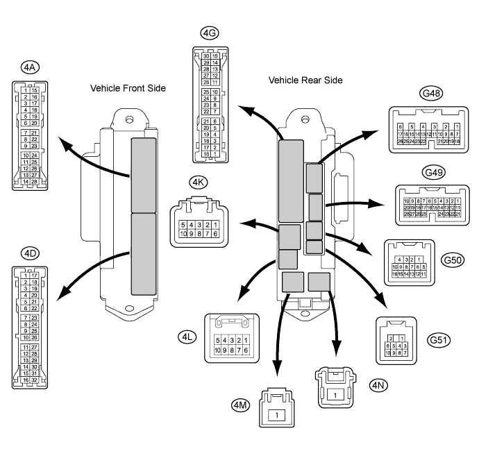
CHECK MAIN BODY ECU
-
Disconnect the 4K, 4A and G50 main body ECU connectors.
-
Measure the voltage and resistance according to the value(s) in the table below.
Tech Tips
Measure the values on the wire harness side with the connector disconnected.
Tester Connection Wiring Color Terminal Description Condition Specified Condition 4K-1 (BECU) - Body ground R - Body ground Battery power supply Always 11 to 14 V 4K-9 (BATB) - Body ground W - Body ground Battery power supply Always 11 to 14 V 4A-3 (GND2) - Body ground W-B - Body ground Ground Always Below 1 Ω G50-1 (GND) - Body ground W-B - Body ground Ground Always Below 1 Ω If the result is not as specified, there may be a malfunction in the wire harness.
-
Reconnect the 4K, 4A and G50 main body ECU connectors.
-
Measure the voltage according to the value(s) in the table below.
Tester Connection Wiring Color Terminal Description Condition Specified Condition G48-24 (DCTY) - Body ground W - Body ground Driver side door courtesy switch input Driver side door open → close Below 1 V → 11 to 14 V G49-21 (PCTY) - Body ground L - Body ground Front passenger side door courtesy switch input Front passenger side door open → close Below 1 V → 11 to 14 V 4A-4 (LCTY) - Body ground R - Body ground Rear door LH courtesy light switch input Rear door LH open → close Below 1 V → Pulse generation G49-7 (RCTY) - Body ground LG - Body ground Rear door RH courtesy light switch input Rear door RH open → close Below 1 V → Pulse generation G49-25*1 (BCTY) - Body ground W - Body ground Back door courtesy light switch input Back door open → Luggage compartment light switch on and back door closed Below 1 V → 11 to 14 V Back door open → Luggage compartment light switch off and back door closed Below 1 V → Pulse generation G49-25*2 (BCTY) - Body ground W - Body ground Back door courtesy light switch input Back door open → closed Below 1 V → Pulse generation 4D-1*3 (ACT+) - Body Ground
4D-5*4 (ACT+) - Body Ground
R - Body Ground Door lock motor lock drive output (Driver side) Multiplex network master switch or driver side door key cylinder off → lock Below 1 V → 11 to 14 V 4D-20*3 (ACT-) - Body Ground
4D-21*4 (ACT-) - Body Ground
W - Body Ground Door lock motor unlock drive output (Driver side) Multiplex network master switch or driver side door key cylinder off → unlock Below 1 V → 11 to 14 V 4D-5*3 (ACT+) - Body Ground
4D-1*4 (ACT+) - Body
B - Body Ground Door lock motor lock drive output (Passenger side) Multiplex network master switch or driver side door key cylinder off → lock Below 1 V → 11 to 14 V 4D-21*3 (ACT-) - Body Ground
4D-20*4 (ACT-) - Body Ground
W - Body Ground Door lock motor unlock drive output (Passenger side) Multiplex network master switch or driver side door key cylinder off → unlock Below 1 V → 11 to 14 V 4D-4 (ACT+) - Body Ground GR - Body Ground Door lock motor lock drive output (Rear right door) Multiplex network master switch or driver side door key cylinder off → lock Below 1 V → 11 to 14 V 4D-21 (ACT-) - Body Ground W- Body Ground Door lock motor lock drive output (Rear right door) Multiplex network master switch or driver side door key cylinder off → unlock Below 1 V → 11 to 14 V 4G-7 (ACT+) - Body Ground R - Body Ground Door lock motor lock drive output (Rear left door) Multiplex network master switch or driver side door key cylinder off → lock Below 1 V → 11 to 14 V 4G-23 (ACT-) - Body Ground BR - Body Ground Door lock motor unlock drive output (Rear left door) Multiplex network master switch or driver side door key cylinder off → unlock Below 1 V → 11 to 14 V G48-9 (LSWD) - Body Ground SB - Body Ground Driver side door position switch input Driver side door unlock → lock Below 1 V → 11 to 14 V G49-27 (LSWP) - Body ground R - Body ground Passenger side door lock position switch input Passenger side door unlock→lock Below 1 V → 11 to 14 V 4D-6 (LSWL) - Body ground SB - Body ground Rear door LH lock position switch input Rear door LH unlock → lock Below 1 V → 11 to 14 V G49-5 (LSWR) - Body ground Y - Body ground Rear door RH lock position switch input Rear door RH unlock → lock Below 1 V → 11 to 14 V 4A-7 (GSW) - Body ground L - Body ground Center airbag sensor signal Turning the engine switch on (IG) with the center airbag sensor assembly connector disconnected 2.8 to 4.3 V
-
*1: w/o Back Door Closer
-
*2: w/ Back Door Closer
-
*3: for RHD
-
*4: for LHD
If the result is not as specified, the main body ECU may have a malfunction.
-
-