CHARGING SYSTEM, Diagnostic DTC:P1550, P1551, P1552

| DTC Code | DTC Name |
|---|---|
| P1550 | Battery Current Sensor Circuit |
| P1551 | Battery Current Sensor Circuit Low |
| P1552 | Battery Current Sensor Circuit High |
DESCRIPTION
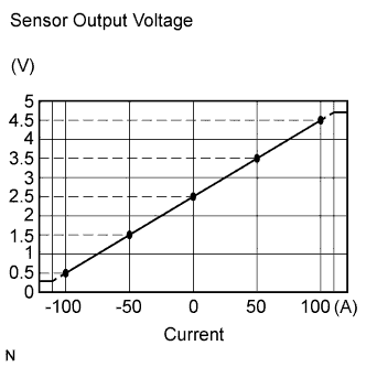
The battery current sensor assembly installed on the negative (-) battery terminal detects the amount of current supplied from the generator.
The battery current sensor assembly changes current to voltage (at the negative (-) battery terminal) and sends it to the ECM. The ECM controls the voltage of the generator based on the signals from the battery current sensor assembly.
| DTC No. | DTC Detection Condition | Trouble Area |
|---|---|---|
| P1550 | Difference between the maximum and minimum current values of the battery current sensor is 1 A or less for 10 seconds or more (1 trip detection logic) |
|
| P1551 | Battery current sensor output value is 0.2 V or less for 0.5 seconds or more with the engine switch on (IG) (1 trip detection logic) |
|
| P1552 | Battery current sensor output value is 4.8 V or more for 0.5 seconds or more with the engine switch on (IG) (1 trip detection logic) |
|
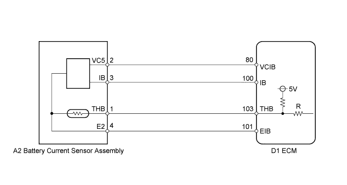
WIRING DIAGRAM
INSPECTION PROCEDURE
Tech Tips
Read freeze frame data using the intelligent tester. The ECM records vehicle and driving condition information as freeze frame data the moment a DTC is stored. When troubleshooting, freeze frame data can be helpful in determining whether the vehicle was running or stopped, whether the engine was warmed up or not, whether the air fuel ratio was lean or rich, as well as other data recorded at the time of a malfunction.
PROCEDURE
-
CHECK ANY OTHER DTCS OUTPUT (IN ADDITION TO P1550, P1551, P1552)
-
Connect the intelligent tester to the DLC3.
-
Turn the engine switch on (IG).
-
Turn the tester on.
-
Enter the following menus: Powertrain / Engine / DTC.
-
Read the DTC.
Result Result Proceed to DTC P1550, P1551 and P1552 are output A DTC P1550, P1551, P1552 and other DTCs are output B Tech Tips
If any DTCs other than P1550, P1551, P1552 are output, troubleshoot those DTCs first.
B 
GO TO DTC CHART Click here
A 
-
-
READ VALUE USING INTELLIGENT TESTER (BATTERY CURRENT)
-
Turn the all electrical systems (headlights, blower motor, rear defogger, etc.) off.
-
Enter the following menus: Powertrain / Engine / Data List / Battery Current.
Result Result Proceed to Battery current is fixed at 0 A, or fluctuates by +/- 1 A or less between -98 and 98 A A Battery current fluctuates between -20 and 0A B
B
CHECK FOR INTERMITTENT PROBLEMS (FOR SFI SYSTEM) Click here
A
-
-
INSPECT BATTERY CURRENT SENSOR ASSEMBLY
-
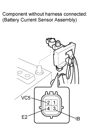
Disconnect the cable from the negative (-) battery terminal.
-
Disconnect the battery current sensor assembly connector.
-
Measure the resistance according to the value(s) in the table below.
Standard Resistance Tester Connection Condition Specified Condition 2 (VC5) - 4 (E2) Always 0.1 to 10 kΩ 2 (VC5) - 3 (IB) Always Below 0.5 kΩ 3 (IB) - 4 (E2) Always 0.05 to 10 kΩ -
Reconnect the cable to the negative (-) battery terminal.
NG
REPLACE BATTERY CURRENT SENSOR ASSEMBLY Click here
OK
-
-
CHECK HARNESS AND CONNECTOR (BATTERY CURRENT SENSOR ASSEMBLY - ECM)
-
Disconnect the ECM connector.
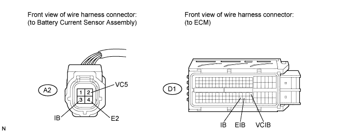
-
Measure the resistance according to the value(s) in the table below.
Standard Resistance (Check for Open) Tester Connection Condition Specified Condition A2-3 (IB) - D1-100 (IB) Always Below 1 Ω A2-2 (VC5) - D1-80 (VCIB) Always Below 1 Ω A2-4 (E2) - D1-101 (EIB) Always Below 1 Ω Standard Resistance (Check for Short) Tester Connection Condition Specified Condition A2-3 (IB) or D1-100 (IB) - Body ground Always 10 kΩ or higher A2-2 (VC5) or D1-80 (VCIB) - Body ground Always 10 kΩ or higher
NG
REPAIR OR REPLACE HARNESS OR CONNECTOR (BATTERY CURRENT SENSOR ASSEMBLY - ECM)
OK 
REPLACE ECM Click here
-