CHARGING SYSTEM, Diagnostic DTC:P0516, P0517

| DTC Code | DTC Name |
|---|---|
| P0516 | Battery Temperature Sensor Circuit Low |
| P0517 | Battery Temperature Sensor Circuit High |
DESCRIPTION
The battery temperature sensor installed on the battery current sensor assembly detects battery temperature.
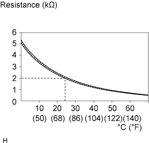
A thermistor is integrated into the battery temperature sensor, and the resistance in the battery temperature sensor changes according to the battery temperature.
The resistance of the thermistor in the battery temperature sensor decreases as the battery temperature increases. The resistance increases as the temperature decreases.
The battery temperature sensor is connected to the ECM. The ECM supplies 5 V from the THB terminal to the battery temperature sensor through resistor R.
The battery temperature sensor and resistor R are connected in series. This results in fluctuations in the voltage supplied from the THB terminal when the resistance changes according to the battery temperature.
The ECM determines the battery temperature according to fluctuations in voltage. When the battery temperature is high, the ECM determines to reduce the amount of current supplied from the generator in order to protect the battery.
| DTC No. | DTC Detection Condition | Trouble Area |
|---|---|---|
| P0516 | Battery temperature sensor output value is 0.2 V or less for 0.5 seconds or more with the engine switch on (IG) (1 trip detection logic) |
|
| P0517 | Battery temperature sensor output value is 4.8 V or more for 0.5 seconds or more with the engine switch on (IG) (1 trip detection logic) |
|
WIRING DIAGRAM
Refer to DTC P1550 Click here.
INSPECTION PROCEDURE
PROCEDURE
-
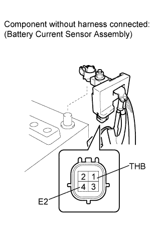
INSPECT BATTERY CURRENT SENSOR ASSEMBLY
-
Disconnect the cable from the negative (-) battery terminal.
-
Disconnect the battery current sensor assembly connector.
-
Measure the resistance according to the value(s) in the table below.
Standard Resistance Tester Connection Condition Specified Condition 1 (THB) - 4 (E2) 20 to 30°C (68 to 36°F) 1.3 to 3.0 kΩ -
Reconnect the cable to the negative (-) battery terminal.
NG 
REPLACE BATTERY CURRENT SENSOR ASSEMBLY Click here
OK 
-
-
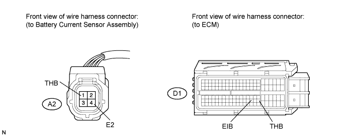
CHECK HARNESS AND CONNECTOR (BATTERY CURRENT SENSOR ASSEMBLY - ECM)
-
Disconnect the ECM connector.
-
Measure the resistance according to the value(s) in the table below.
Standard Resistance (Check for Open) Tester Connection Condition Specified Condition A2-1 (THB) - D1-103 (THB) Always Below 1 Ω A2-4 (E2) - D1-101 (EIB) Always Below 1 Ω Standard Resistance (Check for Short) Tester Connection Condition Specified Condition A2-1 (THB) or D1-103 (THB) - Body ground Always 10 kΩ or higher
NG
REPAIR OR REPLACE HARNESS OR CONNECTOR (BATTERY CURRENT SENSOR ASSEMBLY - ECM)
OK 
REPLACE ECM Click here
-