TOYOTA PARKING ASSIST-SENSOR SYSTEM OPERATION CHECK

-
SELF-CHECK FUNCTION INSPECTION (INITIAL CHECK)
-
Turn the engine switch on (IG).
-
Turn the clearance sonar main switch off (turn the Toyota parking assist-sensor system off), or check that the clearance sonar main switch is off.
-
Turn the engine switch off.
-
Turn the engine switch on (IG).
-
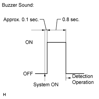
Turn the clearance sonar main switch on (turn the Toyota parking assist-sensor system on), and check that the following occurs:
1) After approximately 0.1 seconds, the buzzer sounds for approximately 0.8 seconds.
2) The system starts detection operation mode.
Tech Tips
-
During the initial check, malfunction detection operates and obstacle detection does not operate.
-
In detection operation mode, obstacle detection and the malfunction detection operate.
-
If a sensor has an open circuit or a sensor malfunctions because it is wet or frozen, a malfunction display is shown in the multi-information display, and the buzzer sounds.
-
If the engine switch is turned on (IG) while the clearance sonar main switch is on, the buzzer does not sound even though malfunction detection operates.
-
-
-
MALFUNCTION DISPLAY (MULTI-INFORMATION DISPLAY)
-
Open circuit indication
-
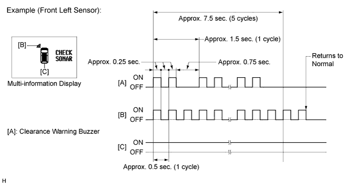
If there is an open circuit between the ultrasonic sensor and the clearance warning ECU assembly or a sensor is malfunctioning, the malfunction is displayed as shown in the illustration.
Tech Tips
-
The example shows an open circuit in the ultrasonic sensor (front left sensor).
-
If a sensor has an open circuit, check for DTCs and troubleshoot according to each inspection procedure Click here.
-
-
-
Frozen indication
-
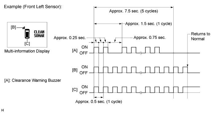
If a sensor is covered with foreign matter, such as mud or snow, the affected sensor is displayed as shown in the illustration.
Tech Tips
-
The example shows that the ultrasonic sensor (front left sensor) is covered with foreign matter.
-
If "CLEAN SONAR" is displayed, refer to "Frozen indication is displayed in self-check function" on Problem Symptoms Table to inspect it Click here.
-
-
-
-
MALFUNCTION DISPLAY (MULTI-DISPLAY)
-
Ultrasonic sensor open circuit
-
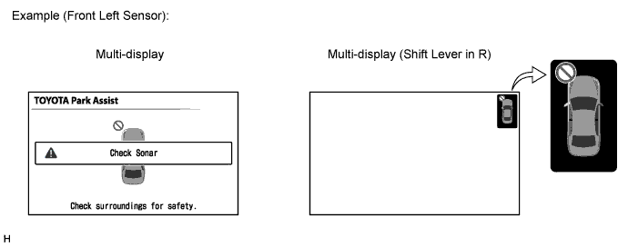
If there is an open circuit between the ultrasonic sensor and the clearance warning ECU assembly or a sensor is malfunctioning, the malfunction is displayed as shown in the illustration.
Tech Tips
-
This example shows an open circuit in the ultrasonic sensor (front left sensor).
-
If a sensor has an open circuit, refer to "Open circuit is displayed during self-check function" on Problem Symptoms Table to inspect it.
-
-
-
Ultrasonic sensor frozen
-
If a sensor is covered with foreign matter, such as mud or snow, the affected sensor is displayed as shown in the illustration.

Tech Tips
-
The example shows that the ultrasonic sensor (front left sensor) is covered with foreign matter.
-
If "Clean Sonar" is displayed, cleaning the foreign matter from the sensor will return the sensor to normal.
-
-
-
-
DETECTION RANGE MEASUREMENT AND DISPLAY INSPECTION
-
Detection range measurement:
Note
Make sure that the vehicle does not move by applying the parking brake firmly.
-
Turn the engine switch on (IG).
-
Move the shift lever to R to check the ultrasonic sensors.
-
-
Turn the clearance sonar main switch on.
-
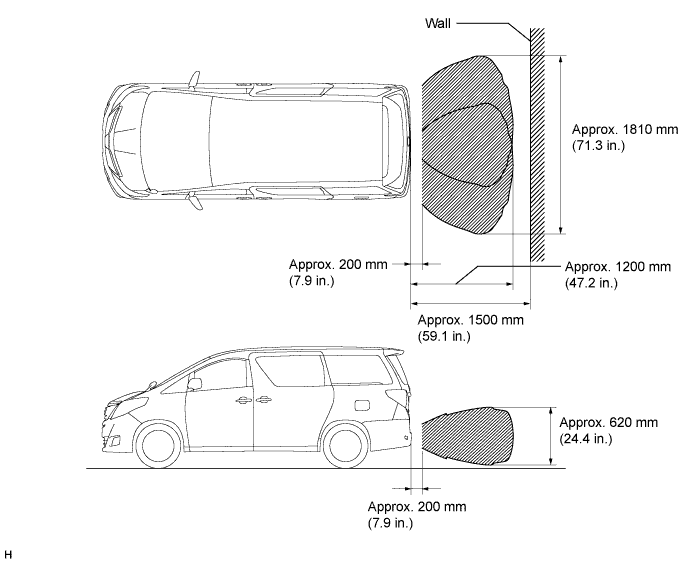
Move a 60 mm (2.4 in.) diameter pole near each sensor to measure its detection range.
Note
These detection ranges are applicable when positioning the 60 mm (2.4 in.) diameter pole parallel or perpendicular to the ground. The detection range varies depending on the measuring method and type of obstacle (such as walls).
Tech Tips
Have an assistant move the pole.
-
Clearance Sonar
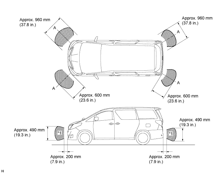
Note
The No. 1 ultrasonic sensor side view detection range hatched area (labeled*1) represents the cross section of the top view of the lines of detection range A. The hatched area *1 does not represent the entire side view detection range.
-
Back Sonar
-
-
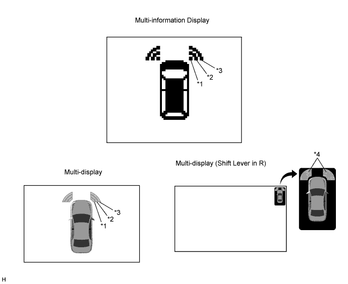
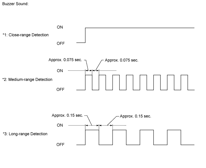
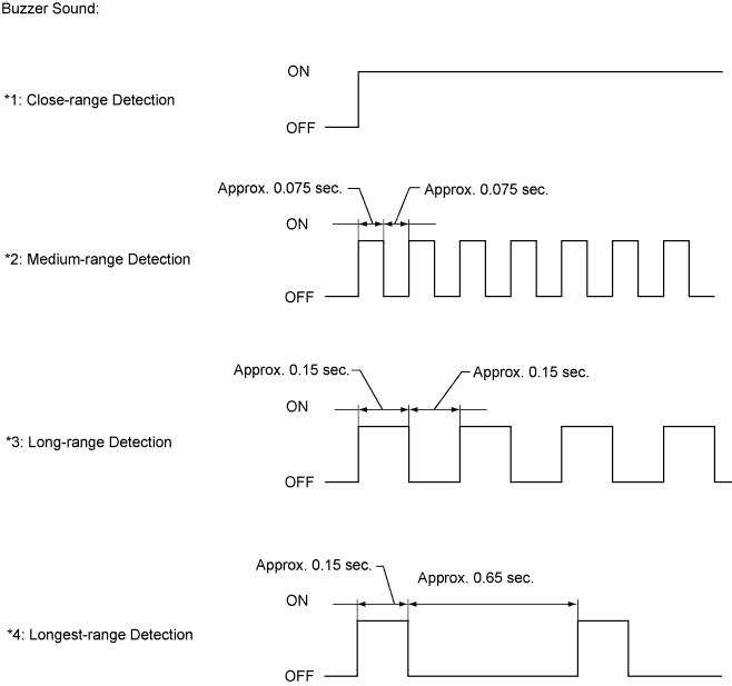
When the ultrasonic sensors (front corner sonar) have detected an obstacle, check the displays and check that the buzzer sounds.
Operation Condition Engine Switch Clearance Sonar Main Switch Shift Lever Position Vehicle Speed On (IG) On In any position other than P
-
Less than approximately 15 km/h (9.3 mph) if speed is increasing
-
Less than approximately 10 km/h (6.2 mph) if speed is decreasing
*5: When a shift lever is not in P or R
Tech Tips
Ultrasonic waves are used to measure the detection range; however, the detection range may vary depending on the ambient temperature.
-
-
When the ultrasonic sensors (rear clearance sonar) have detected an obstacle, check the display and buzzer sounds.
Operation Condition Engine Switch Clearance Sonar Main Switch Shift Lever Position Vehicle Speed On (IG) On R - 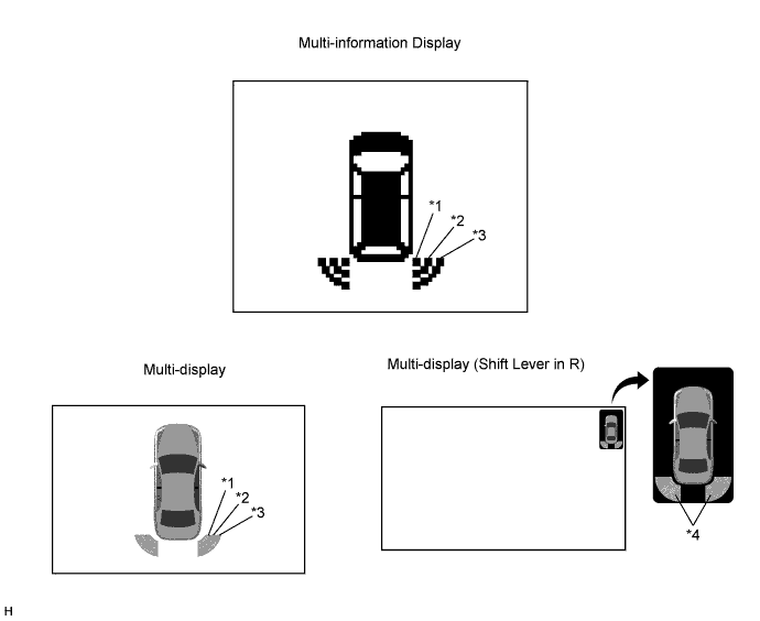
*5: When a shift lever is not in P or R
Tech Tips
Ultrasonic waves are used to measure the detection range; however, the detection range may vary depending on the ambient temperature.
-
When the ultrasonic sensors (back sonar) have detected an obstacle, check the display and buzzer sounds.
Operation Condition Engine Switch Clearance Sonar Main Switch Shift Lever Position Vehicle Speed On (IG) On R - 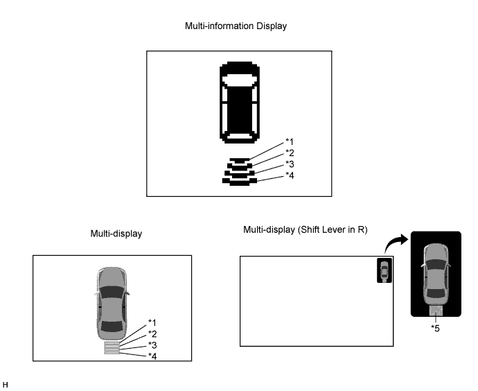
*6: When a shift lever is not in P or R
Tech Tips
Ultrasonic waves are used to measure the detection range; however, the detection range may vary depending on the ambient temperature.
-