NAVIGATION SYSTEM Mute Signal Circuit between Navigation Receiver Assembly and Television Display Assembly
DESCRIPTION
The navigation ECU sub-assembly controls the volume according to the mute signal from the television display assembly.
The mute signal is sent to reduce noise and popping sounds such as those generated when switching modes. If there is an open in the circuit, noise can be heard from the speakers when changing the sound source. If there is a short in the circuit, even though the navigation ECU sub-assembly is functioning normally, no sound or only an extremely faint sound can be heard.
WIRING DIAGRAM
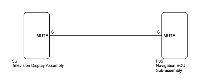
INSPECTION PROCEDURE
Note
Depending on the parts that are replaced during vehicle inspection or maintenance, performing initialization, registration or calibration may be needed. Refer to Precaution for Navigation System Click here.
PROCEDURE
-
INSPECT TELEVISION DISPLAY ASSEMBLY
-
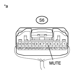
Text in Illustration *a Component with harness connected
(Television Display Assembly)
Measure the voltage according to the value(s) in the table below.
Standard Voltage Tester Connection Condition Specified Condition S6-6 (MUTE) - Body ground Engine switch on (ACC), RSE system playing → Changing source Above 3.5 V → Below 1 V
NG 
CHECK HARNESS AND CONNECTOR (NAVIGATION ECU SUB-ASSEMBLY - TELEVISION DISPLAY ASSEMBLY) Click here
OK 
PROCEED TO NEXT SUSPECTED AREA SHOWN IN PROBLEM SYMPTOMS TABLE Click here
-
-
CHECK HARNESS AND CONNECTOR (NAVIGATION ECU SUB-ASSEMBLY - TELEVISION DISPLAY ASSEMBLY)
-
Disconnect the F35 navigation ECU sub-assembly connector.
-
Disconnect the S6 television display assembly connector.
-
Measure the resistance according to the value(s) in the table below.
Standard Resistance Tester Connection Condition Specified Condition F35-6 (MUTE) - S6-6 (MUTE) Always Below 1 Ω F35-6 (MUTE) - Body ground Always 10 kΩ or higher
NG 
REPAIR OR REPLACE HARNESS OR CONNECTOR
OK 
-
-
REPLACE TELEVISION DISPLAY ASSEMBLY
-
Replace the television display assembly and check if it operates normally Click here.
OK The navigation system operates normally.
NG
REPLACE NAVIGATION ECU SUB-ASSEMBLY Click here
OK
END
-