NAVIGATION SYSTEM Speaker Circuit
DESCRIPTION
-
If there is a short in a speaker circuit, the navigation ECU sub-assembly detects it and stops output to the speakers.
-
Thus sound cannot be heard from the speakers even if there is no malfunction in the navigation ECU sub-assembly or speakers.
w/o Front Center Speaker
-
If there is a short in a speaker circuit, the stereo component amplifier assembly detects it and stops output to the speakers.
-
Thus sound cannot be heard from the speakers even if there is no malfunction in the stereo component amplifier assembly or speakers.
w/ Front Center Speaker
WIRING DIAGRAM
-
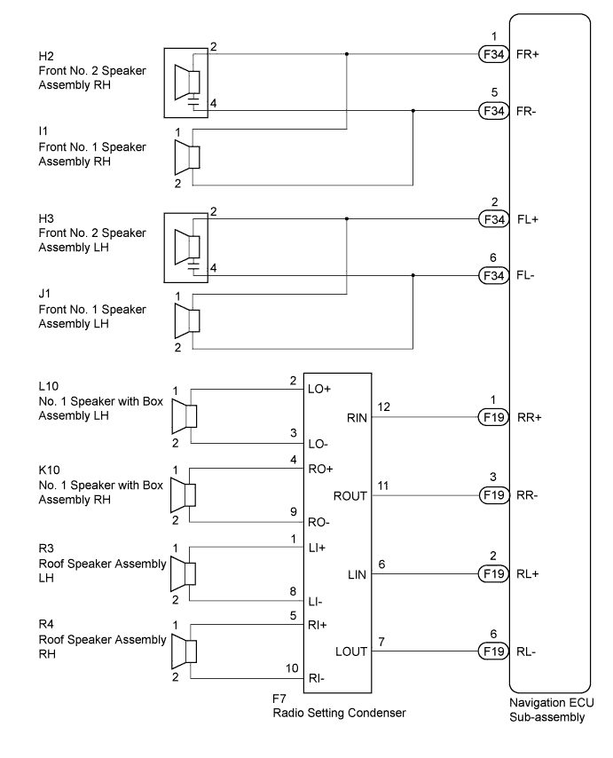
w/o Front Center Speaker
-
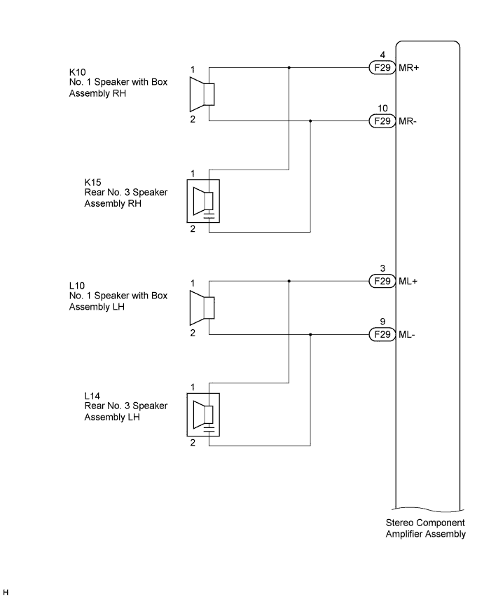
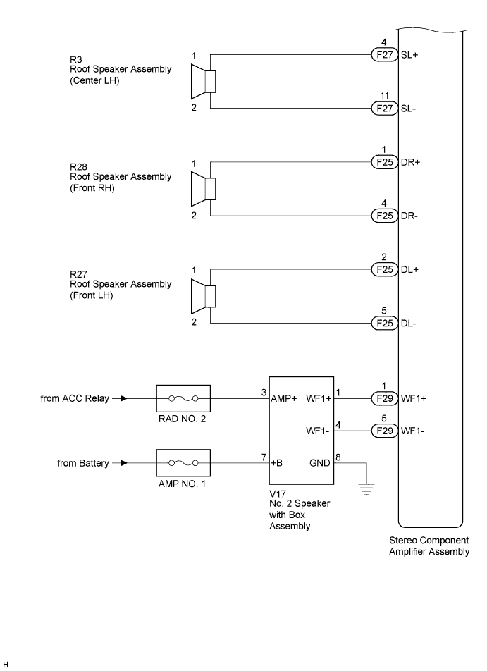
w/ Front Center Speaker
INSPECTION PROCEDURE
Note
Inspect the fuses for circuits related to this system before performing the following inspection procedure.
PROCEDURE
-
CONFIRM MODEL
-
Choose the model to be inspected.
Result Result Proceed to w/o Front Center Speaker A w/ Front Center Speaker B
B 
CHECK HARNESS AND CONNECTOR Click here
A 
-
-
CHECK HARNESS AND CONNECTOR
-
Disconnect the F34 and F19 navigation ECU sub-assembly connectors.
-
Disconnect the J1 and I1 front No. 1 speaker assembly connectors.
-
Disconnect the H2 and H3 front No. 2 speaker assembly connectors.
-
Disconnect the L10 and K10 No. 1 speaker with box assembly connectors.
-
Disconnect the R3 and R4 roof speaker assembly connectors.
-
Disconnect the F7 radio setting condenser connector.
-
Measure the resistance between each of the front No. 2 speaker assemblies and the navigation ECU sub-assembly to check for an open circuit in the wire harness.
Standard Resistance Tester Connection Condition Specified Condition F34-1 (FR+) - H2-2 Always Below 1 Ω F34-5 (FR-) - H2-4 Always Below 1 Ω F34-2 (FL+) - H3-2 Always Below 1 Ω F34-6 (FL-) - H3-4 Always Below 1 Ω -
Measure the resistance between each of the front No. 1 speaker assemblies and the navigation ECU sub-assembly to check for an open circuit in the wire harness.
Standard Resistance Tester Connection Condition Specified Condition F34-1 (FR+) - I1-1 Always Below 1 Ω F34-5 (FR-) - I1-2 Always Below 1 Ω F34-2 (FL+) - J1-1 Always Below 1 Ω F34-6 (FL-) - J1-2 Always Below 1 Ω -
Measure the resistance between the navigation ECU sub-assembly and the radio setting condenser to check for an open circuit in the wire harness.
Standard Resistance Tester Connection Condition Specified Condition F19-1 (RR+) - F7-12 (RIN) Always Below 1 Ω F19-3 (RR-) - F7-11 (ROUT) Always Below 1 Ω F19-2 (RL+) - F7-6 (LIN) Always Below 1 Ω F19-6 (RL-) - F7-7 (LOUT) Always Below 1 Ω -
Measure the resistance between each of the No. 1 speaker with box assemblies and the radio setting condenser to check for an open circuit in the wire harness.
Standard Resistance Tester Connection Condition Specified Condition F7-2 (LO+) - L10-1 Always Below 1 Ω F7-3 (LO-) - L10-2 Always Below 1 Ω F7-4 (RO+) - K10-1 Always Below 1 Ω F7-9 (RO-) - K10-2 Always Below 1 Ω -
Measure the resistance between each of the roof speaker assemblies and the radio setting condenser to check for an open circuit in the wire harness.
Standard Resistance Tester Connection Condition Specified Condition F7-1 (LI+) - R3-1 Always Below 1 Ω F7-8 (LI-) - R3-2 Always Below 1 Ω F7-5 (RI+) - R4-1 Always Below 1 Ω F7-10 (RI-) - R4-2 Always Below 1 Ω -
Measure the resistance between each speaker, navigation ECU sub-assembly and body ground to check for a short circuit in the wire harness.
Standard Resistance Tester Connection Condition Specified Condition H2-2 - Body ground Always 10 kΩ or higher H2-4 - Body ground Always 10 kΩ or higher I1-1 - Body ground Always 10 kΩ or higher I1-2 - Body ground Always 10 kΩ or higher H3-2 - Body ground Always 10 kΩ or higher H3-4 - Body ground Always 10 kΩ or higher J1-1 - Body ground Always 10 kΩ or higher J1-2 - Body ground Always 10 kΩ or higher L10-1 - Body ground Always 10 kΩ or higher L10-2 - Body ground Always 10 kΩ or higher K10-1 - Body ground Always 10 kΩ or higher K10-2 - Body ground Always 10 kΩ or higher R3-1 - Body ground Always 10 kΩ or higher R3-2 - Body ground Always 10 kΩ or higher R4-1 - Body ground Always 10 kΩ or higher R4-2 - Body ground Always 10 kΩ or higher F19-1 (RR+) - Body ground Always 10 kΩ or higher F19-3 (RR-) - Body ground Always 10 kΩ or higher F19-2 (RL+) - Body ground Always 10 kΩ or higher F19-6 (RL-) - Body ground Always 10 kΩ or higher
NG 
REPAIR OR REPLACE HARNESS OR CONNECTOR
OK
-
-
INSPECT FRONT NO. 1 SPEAKER ASSEMBLY
-
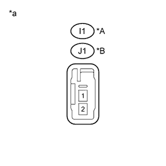
Text in Illustration *A for RH *B for LH *a Component without harness connected
(Front No. 1 Speaker Assembly)
Resistance check
-
Measure the resistance according to the value(s) in the table below.
Standard Resistance Tester Connection Condition Specified Condition I1-1 - I1-2 Always 3.2 to 4.8 Ω J1-1 - J1-2 Always 3.2 to 4.8 Ω
-
NG
REPLACE FRONT NO. 1 SPEAKER ASSEMBLY Click here
OK
-
-
INSPECT FRONT NO. 2 SPEAKER ASSEMBLY
-
Resistance check
-
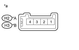
Text in Illustration *A for RH *B for LH *a Component without harness connected
(Front No. 2 Speaker Assembly)
Measure the resistance according to the value(s) in the table below.
Standard Resistance Tester Connection Condition Specified Condition H2-2 - H2-4 Always 10 kΩ or higher H3-2 - H3-4 Always 10 kΩ or higher
-
NG
REPLACE FRONT NO. 2 SPEAKER ASSEMBLY Click here
OK
-
-
REPLACE FRONT NO. 2 SPEAKER ASSEMBLY
-
Check that the malfunction disappears when a known good speaker is installed Click here.
OK Malfunction disappears. Tech Tips
-
Connect all the connectors to the front No. 2 speaker assemblies that were disconnected.
-
When there is a possibility that either the right or left rear speaker is defective, inspect by interchanging the right one with the left one.
-
Perform the above inspection on both LH and RH sides.
-
NG
INSPECT NO. 1 SPEAKER WITH BOX ASSEMBLY Click here
OK 
END (FRONT NO. 2 SPEAKER ASSEMBLY WAS DEFECTIVE)
-
-
INSPECT NO. 1 SPEAKER WITH BOX ASSEMBLY
-
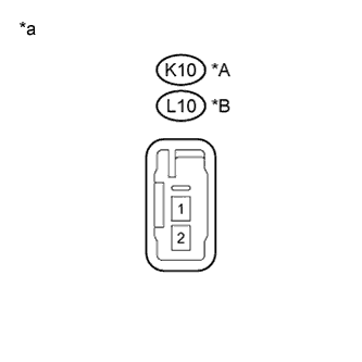
Text in Illustration *A for RH *B for LH *a Component without harness connected
(No. 1 Speaker with Box Assembly)
Resistance check
-
Measure the resistance according to the value(s) in the table below.
Standard Resistance Tester Connection Condition Specified Condition K10-1 - K10-2 Always 3.2 to 4.8 Ω L10-1 - L10-2 Always 3.2 to 4.8 Ω
-
NG
REPLACE NO. 1 SPEAKER WITH BOX ASSEMBLY Click here
OK
-
-
INSPECT ROOF SPEAKER ASSEMBLY (ROOF HEADLINING ASSEMBLY)
-
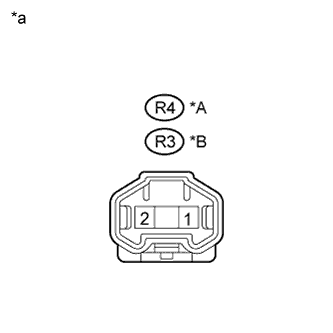
Text in Illustration *A for RH *B for LH *a Component without harness connected
(Roof Speaker Assembly)
Resistance check
-
Measure the resistance according to the value(s) in the table below.
Standard Resistance Tester Connection Condition Specified Condition R4-1 - R4-2 Always 6.4 to 9.6 Ω R3-1 - R3-2 Always 6.4 to 9.6 Ω
-
NG
REPLACE ROOF SPEAKER ASSEMBLY (ROOF HEADLINING ASSEMBLY) Click here
OK
-
-
REPLACE RADIO SETTING CONDENSER
-
Check that the malfunction disappears when a known good radio setting condenser is installed.
OK Malfunction disappears.
NG
PROCEED TO NEXT SUSPECTED AREA SHOWN IN PROBLEM SYMPTOMS TABLE Click here
OK
END (RADIO SETTING CONDENSER WAS DEFECTIVE)
-
-
CHECK HARNESS AND CONNECTOR
-
Disconnect the F25, F26, F27 and F29 stereo component amplifier assembly connectors.
-
Disconnect the K10 and L10 No. 1 speaker with box assembly connectors.
-
Disconnect the K15 and L14 rear No. 3 speaker assembly connectors.
-
Disconnect the I1 and J1 front No. 1 speaker assembly connectors.
-
Disconnect the H7 and H8 front No. 2 speaker assembly connectors.
-
Disconnect the H6 front No. 3 speaker assembly connector.
-
Disconnect the M29 and N35 rear No. 2 speaker assembly connectors.
-
Disconnect the R26 and R25 roof speaker assembly (rear) connectors.
-
Disconnect the R4 and R3 roof speaker assembly (center) connectors.
-
Disconnect the R28 and R27 roof speaker assembly (front) connectors.
-
Disconnect the V17 No. 2 speaker with box assembly connector.
-
Measure the resistance between each of the No. 1 speaker with box assemblies and the stereo component amplifier assembly to check for an open circuit in the wire harness.
Standard Resistance Tester Connection Condition Specified Condition F29-4 (MR+) - K10-1 Always Below 1 Ω F29-10 (MR-) - K10-2 Always Below 1 Ω F29-3 (ML+) - L10-1 Always Below 1 Ω F29-9 (ML-) - L10-2 Always Below 1 Ω -
Measure the resistance between each of the rear No. 3 speaker assemblies and the stereo component amplifier assembly to check for an open circuit in the wire harness.
Standard Resistance Tester Connection Condition Specified Condition F29-4 (MR+) - K15-1 Always Below 1 Ω F29-10 (MR-) - K15-2 Always Below 1 Ω F29-3 (ML+) - L14-1 Always Below 1 Ω F29-9 (ML-) - L14-2 Always Below 1 Ω -
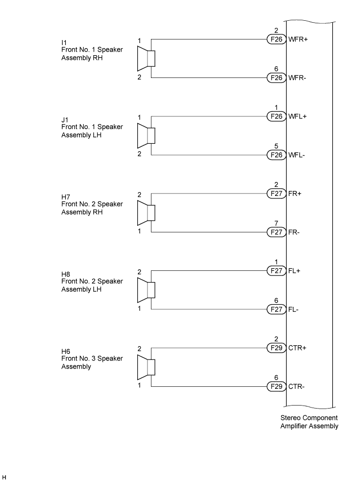
Measure the resistance between each of the front No. 1 speaker assemblies and the stereo component amplifier assembly to check for an open circuit in the wire harness.
Standard Resistance Tester Connection Condition Specified Condition F26-2 (WFR+) - I1-1 Always Below 1 Ω F26-6 (WFR-) - I1-2 Always Below 1 Ω F26-1 (WFL+) - J1-1 Always Below 1 Ω F26-5 (WFL-) - J1-2 Always Below 1 Ω -
Measure the resistance between each of the front No. 2 speaker assemblies and the stereo component amplifier assembly to check for an open circuit in the wire harness.
Standard Resistance Tester Connection Condition Specified Condition F27-2 (FR+) - H7-2 Always Below 1 Ω F27-7 (FR-) - H7-1 Always Below 1 Ω F27-1 (FL+) - H8-2 Always Below 1 Ω F27-6 (FL-) - H8-1 Always Below 1 Ω -
Measure the resistance between the front No. 3 speaker assembly and the stereo component amplifier assembly to check for an open circuit in the wire harness.
Standard Resistance Tester Connection Condition Specified Condition F29-2 (CTR+) - H6-2 Always Below 1 Ω F29-6 (CTR-) - H6-1 Always Below 1 Ω -
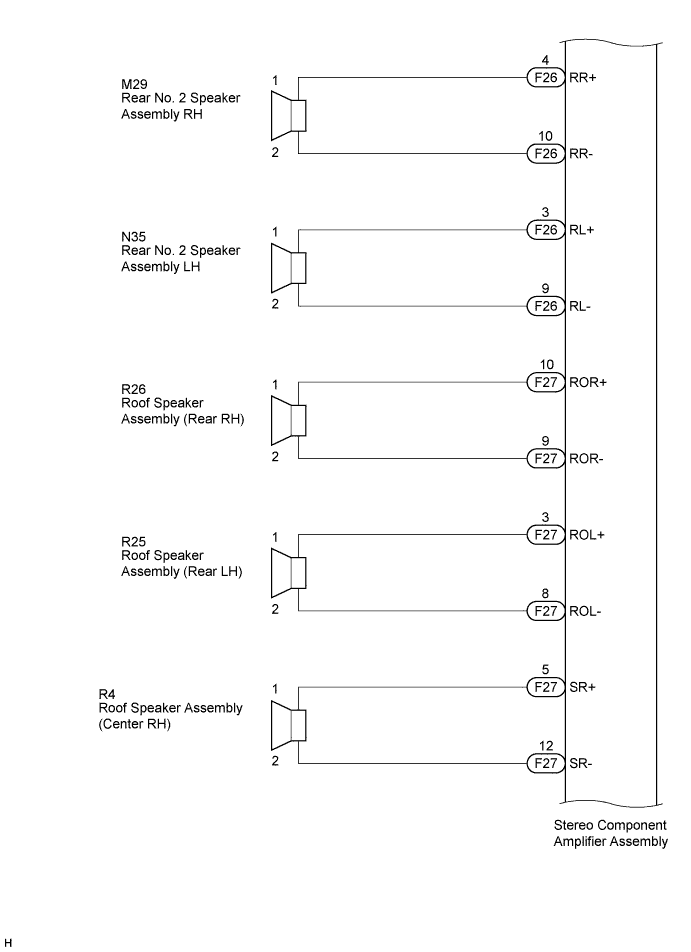
Measure the resistance between each of the rear No. 2 speaker assemblies and the stereo component amplifier assembly to check for an open circuit in the wire harness.
Standard Resistance Tester Connection Condition Specified Condition F26-4 (RR+) - M29-1 Always Below 1 Ω F26-10 (RR-) - M29-2 Always Below 1 Ω F26-3 (RL+) - N35-1 Always Below 1 Ω F26-9 (RL-) - N35-2 Always Below 1 Ω -
Measure the resistance between each of the roof speaker assemblies (rear) and the stereo component amplifier assembly to check for an open circuit in the wire harness.
Standard Resistance Tester Connection Condition Specified Condition F27-10 (ROR+) - R26-1 Always Below 1 Ω F27-9 (ROR-) - R26-2 Always Below 1 Ω F27-3 (ROL+) - R25-1 Always Below 1 Ω F27-8 (ROL-) - R25-2 Always Below 1 Ω -
Measure the resistance between each of the roof speaker assemblies (center) and the stereo component amplifier assembly to check for an open circuit in the wire harness.
Standard Resistance Tester Connection Condition Specified Condition F27-5 (SR+) - R4-1 Always Below 1 Ω F27-12 (SR-) - R4-2 Always Below 1 Ω F27-4 (SL+) - R3-1 Always Below 1 Ω F27-11 (SL-) - R3-2 Always Below 1 Ω -
Measure the resistance between each of the roof speaker assemblies (front) and the stereo component amplifier assembly to check for an open circuit in the wire harness.
Standard Resistance Tester Connection Condition Specified Condition F25-1 (DR+) - R28-1 Always Below 1 Ω F25-4 (DR-) - R28-2 Always Below 1 Ω F25-2 (DL+) - R27-1 Always Below 1 Ω F25-5 (DL-) - R27-2 Always Below 1 Ω -
Measure the resistance between the No. 2 speaker with box assembly and the stereo component amplifier assembly to check for an open circuit in the wire harness.
Standard Resistance Tester Connection Condition Specified Condition F29-1 (WF1+) - V17-1 (WF1+) Always Below 1 Ω F29-5 (WF1-) - V17-4 (WF1-) Always Below 1 Ω -
Measure the resistance between the stereo component amplifier assembly and body ground to check for a short circuit in the wire harness.
Standard Resistance Tester Connection Condition Specified Condition F29-4 (MR+) - Body ground Always 10 kΩ or higher F29-10 (MR-) - Body ground Always 10 kΩ or higher F29-3 (ML+) - Body ground Always 10 kΩ or higher F29-9 (ML-) - Body ground Always 10 kΩ or higher F26-2 (WFR+) - Body ground Always 10 kΩ or higher F26-6 (WFR-) - Body ground Always 10 kΩ or higher F26-1 (WFL+) - Body ground Always 10 kΩ or higher F26-5 (WFL-) - Body ground Always 10 kΩ or higher F27-2 (FR+) - Body ground Always 10 kΩ or higher F27-7 (FR-) - Body ground Always 10 kΩ or higher F27-1 (FL+) - Body ground Always 10 kΩ or higher F27-6 (FL-) - Body ground Always 10 kΩ or higher F29-2 (CTR+) - Body ground Always 10 kΩ or higher F29-6 (CTR-) - Body ground Always 10 kΩ or higher F26-4 (RR+) - Body ground Always 10 kΩ or higher F26-10 (RR-) - Body ground Always 10 kΩ or higher F26-3 (RL+) - Body ground Always 10 kΩ or higher F26-9 (RL-) - Body ground Always 10 kΩ or higher F27-10 (ROR+) - Body ground Always 10 kΩ or higher F27-9 (ROR-) - Body ground Always 10 kΩ or higher F27-3 (ROL+) - Body ground Always 10 kΩ or higher F27-8 (ROL-) - Body ground Always 10 kΩ or higher F27-5 (SR+) - Body ground Always 10 kΩ or higher F27-12 (SR-) - Body ground Always 10 kΩ or higher F27-4 (SL+) - Body ground Always 10 kΩ or higher F27-11 (SL-) - Body ground Always 10 kΩ or higher F25-1 (DR+) - Body ground Always 10 kΩ or higher F25-4 (DR-) - Body ground Always 10 kΩ or higher F25-2 (DL+) - Body ground Always 10 kΩ or higher F25-5 (DL-) - Body ground Always 10 kΩ or higher F29-1 (WF1+) - Body ground Always 10 kΩ or higher F29-5 (WF1-) - Body ground Always 10 kΩ or higher
NG
REPAIR OR REPLACE HARNESS OR CONNECTOR
OK
-
-
INSPECT NO. 1 SPEAKER WITH BOX ASSEMBLY
-
Resistance check
-
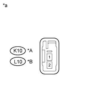
Text in Illustration *A for RH *B for LH *a Component without harness connected
(No. 1 Speaker with Box Assembly)
Measure the resistance according to the value(s) in the table below.
Standard Resistance Tester Connection Condition Specified Condition K10-1 - K10-2 Always 3.2 to 4.8 Ω L10-1 - L10-2 Always 3.2 to 4.8 Ω
-
NG
REPLACE NO. 1 SPEAKER WITH BOX ASSEMBLY Click here
OK
-
-
INSPECT REAR NO. 3 SPEAKER ASSEMBLY
-
Resistance check
-
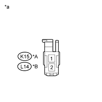
Text in Illustration *A for RH *B for LH *a Component without harness connected
(Rear No. 3 Speaker Assembly)
Measure the resistance according to the value(s) in the table below.
Standard Resistance Tester Connection Condition Specified Condition K15-1 - K15-2 Always 10 kΩ or higher L14-1 - L14-2 Always 10 kΩ or higher
-
NG
REPLACE REAR NO. 3 SPEAKER ASSEMBLY Click here
OK
-
-
REPLACE REAR NO. 3 SPEAKER ASSEMBLY
-
Check that the malfunction disappears when a known good speaker is installed Click here.
OK Malfunction disappears. Tech Tips
-
Connect all the connectors to the rear No. 3 speaker assemblies that were disconnected.
-
When there is a possibility that either the right or left rear speaker is defective, inspect by interchanging the right one with the left one.
-
Perform the above inspection on both LH and RH sides.
-
NG
INSPECT FRONT NO. 1 SPEAKER ASSEMBLY Click here
OK
END (REAR NO. 3 SPEAKER ASSEMBLY WAS DEFECTIVE)
-
-
INSPECT FRONT NO. 1 SPEAKER ASSEMBLY
-
Resistance check
-

Text in Illustration *A for RH *B for LH *a Component without harness connected
(Front No. 1 Speaker Assembly)
Measure the resistance according to the value(s) in the table below.
Standard Resistance Tester Connection Condition Specified Condition I1-1 - I1-2 Always 4.8 to 7.2 Ω J1-1 - J1-2 Always 4.8 to 7.2 Ω
-
NG
REPLACE FRONT NO. 1 SPEAKER ASSEMBLY Click here
OK
-
-
INSPECT FRONT NO. 2 SPEAKER ASSEMBLY
-
Resistance check
-
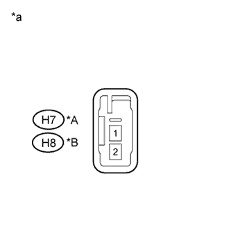
Text in Illustration *A for RH *B for LH *a Component without harness connected
(Front No. 2 Speaker Assembly)
Measure the resistance according to the value(s) in the table below.
Standard Resistance Tester Connection Condition Specified Condition H7-1 - H7-2 Always 3.2 to 4.8 Ω H8-1 - H8-2 Always 3.2 to 4.8 Ω
-
NG
REPLACE FRONT NO. 2 SPEAKER ASSEMBLY Click here
OK
-
-
INSPECT FRONT NO. 3 SPEAKER ASSEMBLY
-
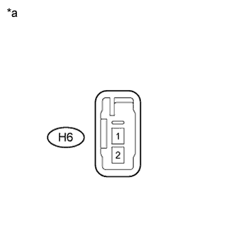
Text in Illustration *a Component without harness connected
(Front No. 3 Speaker Assembly)
Resistance check
-
Measure the resistance according to the value(s) in the table below.
Standard Resistance Tester Connection Condition Specified Condition H6-1 - H6-2 Always 3.2 to 4.8 Ω
-
NG
REPLACE FRONT NO. 3 SPEAKER ASSEMBLY Click here
OK
-
-
INSPECT REAR NO. 2 SPEAKER ASSEMBLY
-
Resistance check
-
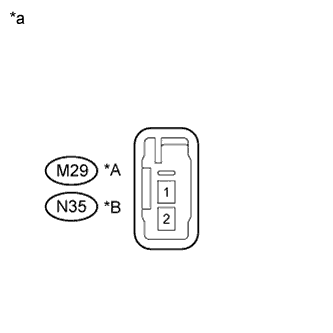
Text in Illustration *A for RH *B for LH *a Component without harness connected
(Rear No. 2 Speaker Assembly)
Measure the resistance according to the value(s) in the table below.
Standard Resistance Tester Connection Condition Specified Condition M29-1 - M29-2 Always 3.2 to 4.8 Ω N35-1 - N35-2 Always 3.2 to 4.8 Ω
-
NG
REPLACE REAR NO. 2 SPEAKER ASSEMBLY Click here
OK
-
-
INSPECT ROOF SPEAKER ASSEMBLY (REAR)
-
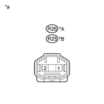
Text in Illustration *A for RH *B for LH *a Component without harness connected
(Roof Speaker Assembly (Rear))
Resistance check
-
Measure the resistance according to the value(s) in the table below.
Standard Resistance Tester Connection Condition Specified Condition R26-1 - R26-2 Always 3.2 to 4.8 Ω R25-1 - R25-2 Always 3.2 to 4.8 Ω
-
NG
REPLACE ROOF SPEAKER ASSEMBLY (REAR) Click here
OK
-
-
INSPECT ROOF SPEAKER ASSEMBLY (CENTER)
-

Text in Illustration *A for RH *B for LH *a Component without harness connected
(Roof Speaker Assembly (Center))
Resistance check
-
Measure the resistance according to the value(s) in the table below.
Standard Resistance Tester Connection Condition Specified Condition R4-1 - R4-2 Always 3.2 to 4.8 Ω R3-1 - R3-2 Always 3.2 to 4.8 Ω
-
NG
REPLACE ROOF SPEAKER ASSEMBLY (CENTER) Click here
OK
-
-
INSPECT ROOF SPEAKER ASSEMBLY (FRONT)
-

Text in Illustration *A for RH *B for LH *a Component without harness connected
(Roof Speaker Assembly (Front))
Resistance check
-
Measure the resistance according to the value(s) in the table below.
Standard Resistance Tester Connection Condition Specified Condition R28-1 - R28-2 Always 3.2 to 4.8 Ω R27-1 - R27-2 Always 3.2 to 4.8 Ω
-
NG
REPLACE ROOF SPEAKER ASSEMBLY (FRONT) Click here
OK
-
-
CHECK HARNESS AND CONNECTOR (NO. 2 SPEAKER WITH BOX ASSEMBLY - BATTERY, BODY GROUND)
-
Disconnect the V17 No. 2 speaker with box assembly connector.
-
Measure the resistance according to the value(s) in the table below.
Standard Resistance Tester Connection Condition Specified Condition V17-8 (GND) - Body ground Always Below 1 Ω -
Measure the voltage according to the value(s) in the table below.
Standard Voltage Tester Connection Condition Specified Condition V17-7 (+B) - V17-8 (GND) Always 11 to 14 V V17-3 (AMP+) - V17-8 (GND) Engine switch on (ACC) 11 to 14 V
NG
REPAIR OR REPLACE HARNESS OR CONNECTOR
OK
-
-
REPLACE NO. 2 SPEAKER WITH BOX ASSEMBLY
-
Check that the malfunction disappears when a known good speaker is installed Click here.
OK Malfunction disappears. Tech Tips
Connect all the connector to the No. 2 speaker with box assembly that was disconnected.
NG
PROCEED TO NEXT SUSPECTED AREA SHOWN IN PROBLEM SYMPTOMS TABLE Click here
OK
END (NO. 2 SPEAKER WITH BOX ASSEMBLY WAS DEFECTIVE)
-