NAVIGATION SYSTEM, Diagnostic DTC:B1579

| DTC Code | DTC Name |
|---|---|
| B1579 | Voice Recognition Microphone Disconnected |
DESCRIPTION
The navigation ECU sub-assembly and telephone microphone assembly are connected to each other using the microphone connection detection signal lines.
This DTC is stored when a microphone connection detection signal line is disconnected.
| DTC No. | DTC Detection Condition | Trouble Area |
|---|---|---|
| B1579 | Telephone microphone signal is lost. |
|
WIRING DIAGRAM
-
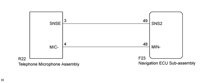
w/ Front Center Speaker
-
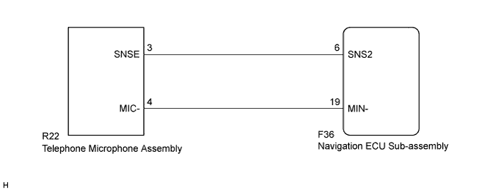
w/o Front Center Speaker
INSPECTION PROCEDURE
Note
Depending on the parts that are replaced during vehicle inspection or maintenance, performing initialization, registration or calibration may be needed. Refer to Precaution for Navigation System Click here.
PROCEDURE
-
CONFIRM MODEL
-
Choose the model to be inspected.
Result Result Proceed to w/ Front Center Speaker A w/o Front Center Speaker B
B 
INSPECT NAVIGATION ECU SUB-ASSEMBLY Click here
A 
-
-
INSPECT NAVIGATION ECU SUB-ASSEMBLY
-
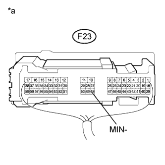
Text in Illustration *a Component with harness connected
(Navigation ECU Sub-assembly)
Measure the resistance according to the value(s) in the table below.
Standard Resistance Tester Connection Condition Specified Condition F23-48 (MIN-) - Body ground Always Below 1 Ω
NG 
REPLACE NAVIGATION ECU SUB-ASSEMBLY Click here
OK
-
-
CHECK HARNESS AND CONNECTOR (NAVIGATION ECU SUB-ASSEMBLY - TELEPHONE MICROPHONE ASSEMBLY)
-
Disconnect the F23 navigation ECU sub-assembly connector.
-
Disconnect the R22 telephone microphone assembly connector.
-
Measure the resistance according to the value(s) in the table below.
Standard Resistance Tester Connection Condition Specified Condition F23-49 (SNS2) - R22-3 (SNSE) Always Below 1 Ω F23-48 (MIN-) - R22-4 (MIC-) Always Below 1 Ω F23-49 (SNS2) - Body ground Always 10 kΩ or higher F23-48 (MIN-) - Body ground Always 10 kΩ or higher -
Proceed to the next step based on the inspection result.
Result Result Proceed to NG A OK B
B
INSPECT TELEPHONE MICROPHONE ASSEMBLY Click here
A 
REPAIR OR REPLACE HARNESS OR CONNECTOR
-
-
INSPECT NAVIGATION ECU SUB-ASSEMBLY
-
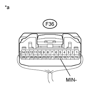
Text in Illustration *a Component with harness connected
(Navigation ECU Sub-assembly)
Measure the resistance according to the value(s) in the table below.
Standard Resistance Tester Connection Condition Specified Condition F36-19 (MIN-) - Body ground Always Below 1 Ω
NG
REPLACE NAVIGATION ECU SUB-ASSEMBLY Click here
OK
-
-
CHECK HARNESS AND CONNECTOR (NAVIGATION ECU SUB-ASSEMBLY - TELEPHONE MICROPHONE ASSEMBLY)
-
Disconnect the F36 navigation ECU sub-assembly connector.
-
Disconnect the R22 telephone microphone assembly connector.
-
Measure the resistance according to the value(s) in the table below.
Standard Resistance Tester Connection Condition Specified Condition F36-6 (SNS2) - R22-3 (SNSE) Always Below 1 Ω F36-19 (MIN-) - R22-4 (MIC-) Always Below 1 Ω F36-6 (SNS2) - Body ground Always 10 kΩ or higher F36-19 (MIN-) - Body ground Always 10 kΩ or higher
NG
REPAIR OR REPLACE HARNESS OR CONNECTOR
OK
-
-
INSPECT TELEPHONE MICROPHONE ASSEMBLY
-
Disconnect the R22 telephone microphone assembly connector.
-
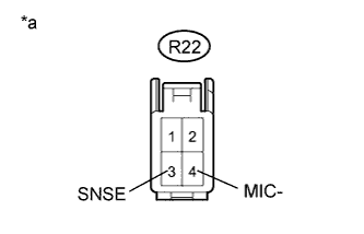
Text in Illustration *a Component without harness connected
(Telephone Microphone Assembly)
Measure the resistance according to the value(s) in the table below.
Standard Resistance Tester Connection Condition Specified Condition R22-3 (SNSE) - R22-4 (MIC-) Always Below 1 Ω
NG
REPLACE TELEPHONE MICROPHONE ASSEMBLY Click here
OK
REPLACE NAVIGATION ECU SUB-ASSEMBLY Click here
-