NAVIGATION SYSTEM Navigation Receiver Assembly Power Source Circuit
DESCRIPTION
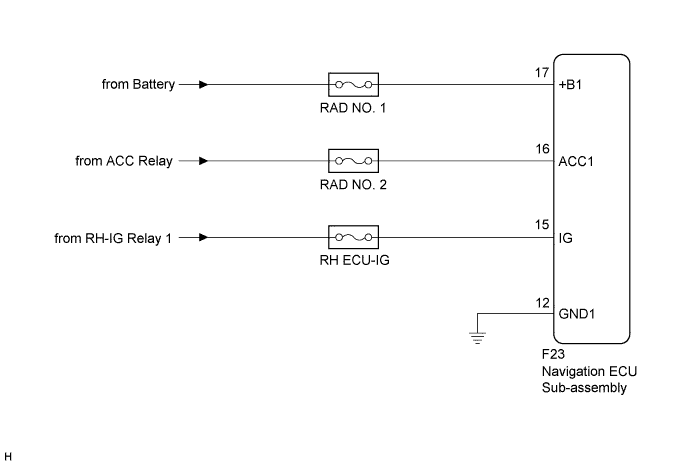
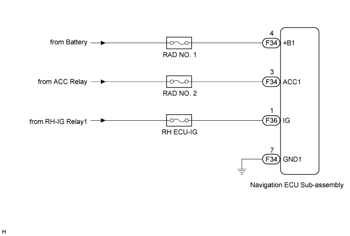
This is the power source circuit to operate the navigation ECU sub-assembly.
WIRING DIAGRAM
-
w/ Front Center Speaker
-
w/o Front Center Speaker
INSPECTION PROCEDURE
Note
Inspect the fuses for circuits related to this system before performing the following inspection procedure.
PROCEDURE
-
CHECK HARNESS AND CONNECTOR (NAVIGATION ECU SUB-ASSEMBLY POWER SOURCE)
-
Disconnect the F23 navigation ECU sub-assembly connector (w/ Front Center Speaker).
-
Disconnect the F34 and F36 navigation ECU sub-assembly connectors (w/o Front Center Speaker).
-
Measure the resistance according to the value(s) in the table below .
Standard Resistance w/ Front Center Speaker Tester Connection Condition Specified Condition F23-12 (GND1) - Body ground Always Below 1 Ω w/o Front Center Speaker Tester Connection Condition Specified Condition F34-7 (GND) - Body ground Always Below 1 Ω -
Measure the voltage according to the value(s) in the table below.
Standard Voltage w/ Front Center Speaker Tester Connection Condition Specified Condition F23-17 (+B1) - F23-12 (GND1) Always 11 to 14 V F23-16 (ACC1) - F23-12 (GND1) Engine switch on (ACC) 11 to 14 V F23-15 (IG) - F23-12 (GND1) Engine switch on (IG) 11 to 14 V w/o Front Center Speaker Tester Connection Condition Specified Condition F34-4 (+B1) - F34-7 (GND) Always 11 to 14 V F34-3 (ACC1) - F34-7 (GND) Engine switch on (ACC) 11 to 14 V F36-1 (IG) - F34-7 (GND) Engine switch on (IG) 11 to 14 V
NG 
REPAIR OR REPLACE HARNESS OR CONNECTOR
OK 
PROCEED TO NEXT SUSPECTED AREA SHOWN IN PROBLEM SYMPTOMS TABLE Click here
-