- Click here
INSPECT FRONT NO. 2 SPEAKER ASSEMBLY (w/o Front Center Speaker)
-
With the speaker installed, check that there is no looseness or other abnormalities.
-
Check that there is no foreign matter in the speaker, no tears on the speaker cone or other abnormalities.
-
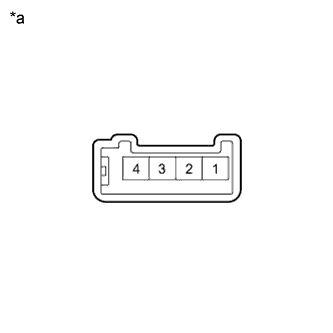
Measure the resistance of the speaker.
Standard Resistance Tester Connection Condition Specified Condition 2 - 4 Always 10 kΩ or higher 1 - 2 Always Below 1 Ω 3 - 4 Always Below 1 Ω If the result is not as specified, replace the speaker.
Table 1. Text in Illustration *a Component without harness connected
(Front No. 2 Speaker Assembly)
-
When there is a possibility that either the right or left speaker is malfunctioning, interchange the speakers and perform an inspection. If the malfunction disappears after interchanging the speakers, replace the malfunctioning speaker.
Tip:Connect all connectors to the speakers when performing an inspection. If the result is not as specified, replace the speaker.
-
- Click here
INSPECT FRONT NO. 2 SPEAKER ASSEMBLY (w/ Front Center Speaker)
Tip:Remove interior parts so that the front No. 2 speaker assembly can be seen.
-
Check the speaker installation.
OK The speaker is securely installed. If the result is not as specified, reinstall the front No. 2 speaker assembly.
-
Visually check the speaker.
OK The cone paper of the speaker is not torn. If the result is not as specified, replace the front No. 2 speaker assembly.
-
Speaker resistance check
-
Disconnect the front No. 2 speaker assembly connector.
-
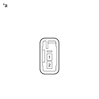
Measure the resistance according to the value(s) in the table below.
Standard Resistance Tester Connection Condition Specified Condition 1 - 2 Always 3.2 to 4.8 Ω If the result is not as specified, replace the front No. 2 speaker assembly.
Table 2. Text in Illustration *a Component without harness connected
(Front No. 2 Speaker Assembly)
-
-
- Click here
INSPECT FRONT NO. 3 SPEAKER ASSEMBLY (w/ Front Center Speaker)
Tip:Remove interior parts so that the front No. 3 speaker assembly can be seen.
-
Check the speaker installation.
OK The speaker is securely installed. If the result is not as specified, reinstall the front No. 3 speaker assembly.
-
Visually check the speaker.
OK The cone paper of the speaker is not torn. If the result is not as specified, replace the front No. 3 speaker assembly.
-
Speaker resistance check
-
Disconnect the front No. 3 speaker assembly connector.
-
Measure the resistance according to the value(s) in the table below.
Standard Resistance Tester Connection Condition Specified Condition 1 - 2 Always 3.2 to 4.8 Ω If the result is not as specified, replace the front No. 3 speaker assembly.
Table 3. Text in Illustration *a Component without harness connected
(Front No. 3 Speaker Assembly)
-
-