STEERING GEAR REMOVAL

-
PLACE FRONT WHEELS FACING STRAIGHT AHEAD
-
SECURE STEERING WHEEL
-
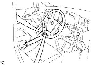
Secure the steering wheel with the seat belt in order to prevent rotation.
Tech Tips
This operation is useful to prevent damage to the spiral cable.
-
-
REMOVE COLUMN HOLE COVER SILENCER SHEET
-
Remove the 2 clips and column hole cover silencer sheet.
-
-
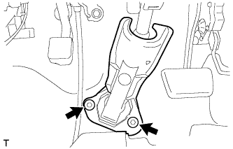
SEPARATE NO. 2 STEERING INTERMEDIATE SHAFT ASSEMBLY
-
Remove the bolt from the No. 2 steering intermediate shaft assembly.
-
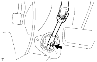
Slide the No. 2 steering intermediate shaft assembly toward the steering column assembly.
Note
Do not separate the No. 2 steering intermediate shaft assembly from the steering intermediate shaft assembly.
-
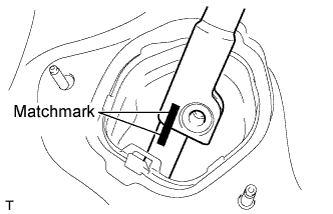
Put matchmarks on the No. 2 steering intermediate shaft assembly and the steering intermediate shaft assembly.
-
Separate the No. 2 steering intermediate shaft assembly from the steering intermediate shaft assembly.
-
-
SEPARATE NO. 1 STEERING COLUMN HOLE COVER SUB-ASSEMBLY
-
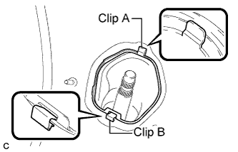
Push clip B towards center of the hole to release it, then push on clip A and remove the No. 1 steering column hole cover sub-assembly from the body.
Note
Do not damage clip A and B.
-
-
REMOVE FRONT WHEELS
-
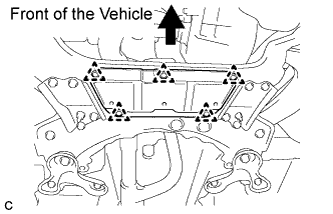
REMOVE NO. 2 ENGINE UNDER COVER (for Rear Side)
-
Remove the 4 clips and the No. 2 engine under cover.
-
-
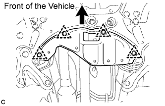
REMOVE NO. 2 ENGINE UNDER COVER (for Front Side)
-
Remove the 5 clips and the No. 2 engine under cover.
-
-
REMOVE NO. 1 ENGINE UNDER COVER
-
REMOVE ENGINE UNDER COVER
-
REMOVE REAR ENGINE UNDER COVER LH
-
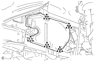
Remove the 5 clips and the rear engine under cover LH.
-
-
REMOVE REAR ENGINE UNDER COVER RH
Tech Tips
Perform the same procedure as for the LH side.
-
REMOVE FRONT SUSPENSION MEMBER REINFORCEMENT LH
-
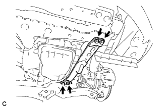
Remove the 4 bolts and the front suspension member reinforcement LH.
-
-
REMOVE FRONT SUSPENSION MEMBER REINFORCEMENT RH
Tech Tips
Perform the same procedure as for the LH side.
-
SEPARATE FRONT STABILIZER LINK ASSEMBLY LH
-
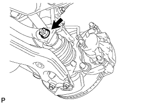
Remove the nut and separate the front stabilizer link assembly LH.
Note
If the ball joint turns together with the nut, use a hexagon wrench (6 mm) to hold the stud.
-
-
SEPARATE FRONT STABILIZER LINK ASSEMBLY RH
Tech Tips
Perform the same procedure as for the LH side.
-
SEPARATE TIE ROD END SUB-ASSEMBLY LH
-
Remove the cotter pin and nut.
-
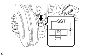
Install SST to the tie rod end.
- SST
- 09960-20010 ( 09961-02060 )
Note
Make sure that the upper end of the tie rod end and SST are aligned.
-
Using SST, separate the tie rod end from the steering knuckle.
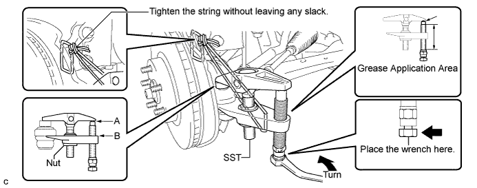
- SST
- 09960-20010 ( 09961-02010 )
CAUTION:
Apply grease to the bolt threads and the tip of SST.
Note
-
Be sure to tighten the string firmly to secure SST to the steering knuckle to prevent SST from falling off.
-
Install SST with the center nut so that A and B shown in the illustration are parallel. Otherwise, the dust cover may be damaged.
-
Be sure to place the wrench on the part indicated in the illustration.
-
Do not damage the front disc brake dust cover.
-
Do not damage the ball joint dust cover.
-
Do not damage the steering knuckle.
-
-
SEPARATE TIE ROD END SUB-ASSEMBLY RH
Tech Tips
Perform the same procedure as for the LH side.
-
SEPARATE FRONT LOWER SUSPENSION ARM SUB-ASSEMBLY LH
-
Remove the bolt and 2 nuts, and separate the front lower suspension arm sub-assembly LH from the lower ball joint.
-
-
SEPARATE FRONT LOWER SUSPENSION ARM SUB-ASSEMBLY RH
Tech Tips
Perform the same procedure as for the LH side.
-
REMOVE FRONT SUSPENSION MEMBER BRACE SUB-ASSEMBLY
-
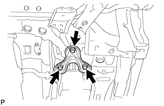
Remove the 3 bolts and front suspension member brace sub-assembly (LH side).
-
Perform the same procedure for the front suspension member brace sub-assembly (RH side).
-
-
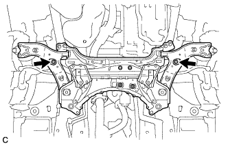
REMOVE FRONT SUSPENSION CROSSMEMBER SUB-ASSEMBLY
-
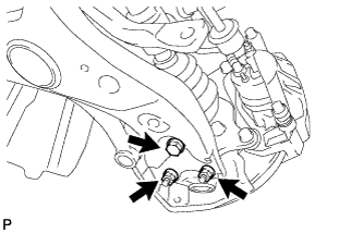
Remove the 2 bolts and 2 nuts, and separate the front suspension crossmember sub-assembly from the rear engine mounting insulator.
-
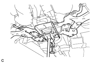
Using a transmission jack or equivalent, support the front suspension crossmember sub-assembly.
-
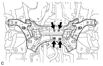
Remove the 2 bolts.
-
Slowly lower the jack, and remove the front suspension crossmember sub-assembly from the vehicle.
-
-
REMOVE NO. 1 STEERING COLUMN HOLE COVER SUB-ASSEMBLY
-
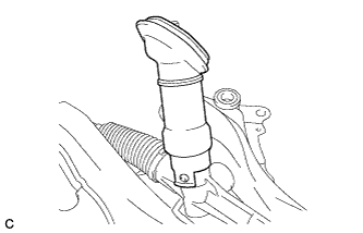
Remove the No. 1 steering column hole cover sub-assembly from the steering link assembly.
-
-
REMOVE STEERING INTERMEDIATE SHAFT
-
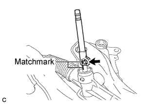
Put matchmarks on the steering intermediate shaft and steering link assembly.
-
Remove the bolt and steering intermediate shaft from the steering link assembly.
-
-
REMOVE STEERING LINK ASSEMBLY
-
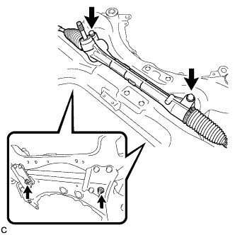
Remove the 2 bolts, 2 nuts and steering link assembly from the front suspension crossmember sub-assembly.
Note
Keep the nut from rotating while turning the bolt because the nut has its own stopper.
-
-
SECURE STEERING LINK ASSEMBLY
-
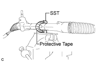
Using SST, secure the steering link assembly in a vise.
- SST
- 09612-00012
Tech Tips
Tape SST before use.
-
-
REMOVE TIE ROD END SUB-ASSEMBLY LH
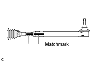
-
Put matchmarks on the tie rod end sub-assembly LH and steering gear assembly.
-
Remove the tie rod end sub-assembly LH and lock nut.
-
-
REMOVE TIE ROD END SUB-ASSEMBLY RH
Tech Tips
Perform the same procedure as for the LH side.