- Click here
INSTALL POWER STEERING MOTOR ASSEMBLY
Note:
-
Do not drop the power steering motor assembly, strike it with tools or subject it to impacts.
-
If the power steering motor assembly is subjected to an impact, replace it with a new one.
-
Do not pull the wire harness of the power steering motor assembly.
-
Do not allow any moisture to come into contact with the power steering motor assembly.
-
Do not loosen any bolts not mentioned in the procedure.
-
Install a new electric power steering motor shaft damper to the electric power steering column sub-assembly.
-
Install a new electric power steering motor shaft spacer to the electric power steering column sub-assembly.
-
Temporarily install the power steering motor assembly to the electric power steering column sub-assembly with the 2 bolts.
Note:When temporarily installing the 2 bolts to the power steering motor assembly, do not tighten them all the way down.
-
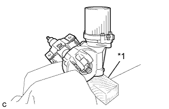
Secure the steering column assembly in a vice using aluminum plates and a piece of cloth.
Table 1. Text in Illustration *1 Wooden Block Note:
-
Do not overtighten the vice, as the steering column assembly may become deformed.
-
Secure the power steering motor assembly so that it is directly upright.
-
Support the steering column assembly with a wooden block or similar item to ensure that it does not fall.
-
-
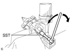
Using SST, turn the steering main shaft once 180 degrees to the left and then 180 degrees to the right at a speed of 60 rpm, and repeat 2 to 3 times to adjust the axis centering of the power steering motor assembly.
09616-00011 -
Tighten the 2 bolts.
19 N*m 189 kgf*cm 14 ft.*lbf -
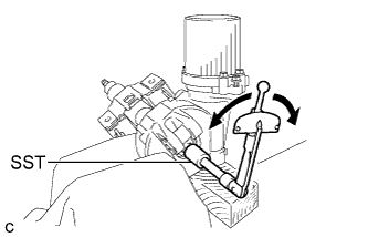
Measure the turning torque of the steering main shaft using SST.
09616-00011 Turning torque 0.8 to 1.2 N*m 9 to 12 kgf*cm 8 to 10 in.*lbf Note:Ensure that there is no abnormal resistance during rotation.
If the torque is not as specified, readjust the axis centering of the power steering motor assembly.
-
Remove the steering column assembly from the vice.
-
Engage the claw to install the torque sensor harness connector.
-
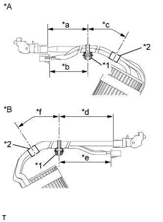
Install new clamp and tape to the wire harness as shown in the illustration.
Table 2. Text in Illustration *A for RHD *B for LHD *1 Clamp *2 Tape *a 270 to 290 mm *b 245 to 265 mm *c 65 to 105 mm *d 270 to 290 mm *e 245 to 265 mm *f 65 to 105 mm Note:Wrap the tape more than 2 times.
-
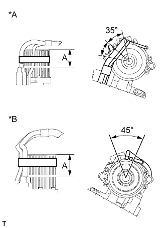
Tape the wire harness to the power steering motor assembly as shown in the illustration.
Table 3. Text in Illustration *A for RHD *B for LHD Note:
-
Wrap the tape around the area marked as "A" in the illustration more than 2 times.
-
As heat from the power steering motor assembly may generate smoke, use heat resistant tape (resistant to 100°C (212°F) or more).
-
-
- Click here
INSTALL STEERING LOCK ACTUATOR ASSEMBLY
-
Secure the steering column assembly in a vise.
Note:Do not overtighten the vise.
-
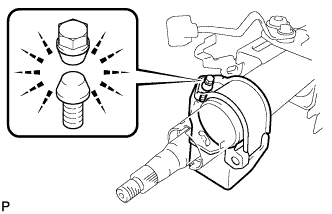
Temporarily install the steering lock actuator assembly to the steering column assembly with a new tapered-head bolt.
-
Tighten the tapered-head bolt until the bolt head breaks off.
-
- Click here
INSTALL NO. 2 STEERING INTERMEDIATE SHAFT ASSEMBLY
-
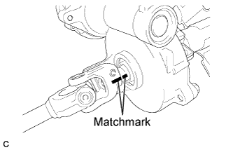
Align the matchmarks on the No. 2 steering intermediate shaft assembly and steering column assembly.
-
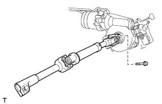
Install the No. 2 steering intermediate shaft assembly to the steering column assembly with the bolt.
35 N*m 360 kgf*cm 26 ft.*lbf
-