STEERING COLUMN ASSEMBLY DISASSEMBLY

-
REMOVE NO. 2 STEERING INTERMEDIATE SHAFT ASSEMBLY
-
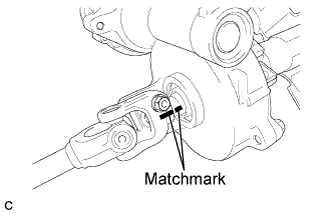
Put matchmarks on the No. 2 steering intermediate shaft assembly and steering column assembly.
-
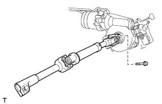
Remove the bolt and No. 2 steering intermediate shaft assembly from the steering column assembly.
-
-
REMOVE STEERING LOCK ACTUATOR ASSEMBLY
-
Secure the steering column assembly in a vise.
Note
Do not overtighten the vise.
-
Using a center punch, mark the center of the tapered-head bolt.
-
Using a 3 to 4 mm (0.118 to 0.157 in.) diameter drill bit, drill a hole in the tapered-head bolt.
-
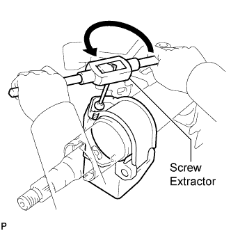
Using a screw extractor, remove the tapered-head bolt and steering lock actuator assembly from the steering column assembly.
-
-
REMOVE POWER STEERING MOTOR ASSEMBLY
Note
-
Do not drop the power steering motor assembly, strike it with tools or subject it to impacts.
-
If the power steering motor assembly is subjected to an impact, replace it with a new one.
-
Do not pull the wire harness of the power steering motor assembly.
-
Do not allow any moisture to come into contact with the power steering motor assembly.
-
Do not loosen any bolts not mentioned in the procedure.
-
Remove the tape and clamp of the wire harness.
-
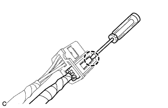
Using a screwdriver, disengage the claw to remove the torque sensor harness connector.
-
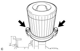
Remove the 2 bolts and power steering motor assembly from the electric power steering column sub-assembly.
-

Remove the electric power steering motor shaft spacer from the electric power steering column sub-assembly.
-
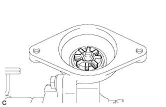
Remove the electric power steering motor shaft damper from the electric power steering column sub-assembly.
-