DESCRIPTION
This circuit supplies voltage from the battery to terminal B of the steering lock ECU. This circuit is used as power source for the steering lock ECU, motor, communication and peripheral circuits.
INSPECTION PROCEDURE
-
When the engine switch is off, the main body ECU may occasionally go into a non-active state called sleep mode. Therefore, before proceeding with the inspection, it is necessary to perform the following step to wake up the ECU:
Before starting the inspection, with the engine switch off, open the driver door. Then (with the engine switch still off) open and close any door several times at 1.5-second intervals.
-
After replacing the steering lock actuator assembly (steering lock ECU), confirm the lock/unlock operation of the steering lock (Click here).
PROCEDURE
- Click here
CHECK HARNESS AND CONNECTOR (STEERING LOCK ACTUATOR ASSEMBLY - BODY GROUND)
-
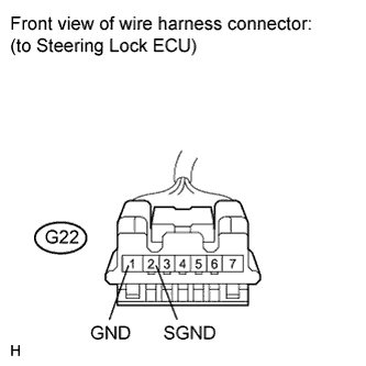
Disconnect the G22 connector from the steering lock actuator assembly.
-
Measure the resistance according to the value(s) in the table below.
Standard Resistance Tester Connection Condition Specified Condition G22-1 (GND) - Body ground Always Below 1 Ω G22-2 (SGND) - Body ground Always Below 1 Ω
- OKClick here
- NGClick here
-
- Click here
CHECK HARNESS AND CONNECTOR (STEERING LOCK ACTUATOR ASSEMBLY - BATTERY)
-
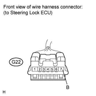
Measure the voltage according to the value(s) in the table below.
Standard Voltage Tester Connection Condition Specified Condition G22-7 (B) - Body ground Always 11 to 14 V
- OKClick here
- NGClick here
-
- Click here
REPAIR OR REPLACE HARNESS OR CONNECTOR (STEERING LOCK ACTUATOR ASSEMBLY - BATTERY)
- Click here
REPAIR OR REPLACE HARNESS OR CONNECTOR
- Click here
PROCEED TO NEXT SUSPECTED AREA SHOWN IN PROBLEM SYMPTOMS TABLEClick here