STEERING LOCK SYSTEM Unlock Position Sensor Signal Circuit
DESCRIPTION
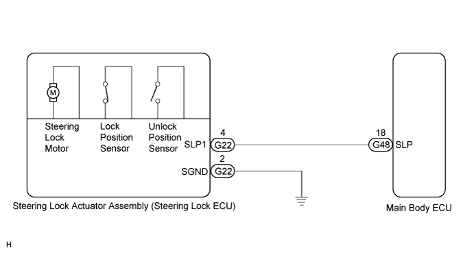
The unlock position sensor is one of the components of the steering lock actuator assembly. The sensor switch contact closes when the steering lock is released. The steering lock release signal is then sent to the main body ECU. Receiving the signal, the ECU permits engine starting. (This prevents the engine from being started with the steering locked.)
WIRING DIAGRAM
INSPECTION PROCEDURE
Tech Tips
-
When the engine switch is off, the main body ECU may occasionally go into a non-active state called sleep mode. Therefore, before proceeding with the inspection, it is necessary to perform the following step to wake up the ECU:
Before starting the inspection, with the engine switch off, open the driver door. Then (with the engine switch still off) open and close any door several times at 1.5-second intervals.
-
After replacing the steering lock actuator assembly (steering lock ECU), confirm the lock/unlock operation of the steering lock Click here.
PROCEDURE
-
INSPECT STEERING LOCK ACTUATOR ASSEMBLY (STEERING LOCK ECU)
-
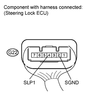
Measure the voltage according to the value(s) in the table below.
Standard Voltage Tester Connection Switch Condition Specified Condition G22-4 (SLP1) - G22-2 (SGND)
-
Engine switch off
-
Engine switch on (ACC or IG)
Below 1 V -
NG 
CHECK HARNESS AND CONNECTOR (STEERING LOCK ACTUATOR ASSEMBLY - MAIN BODY ECU) Click here
OK 
CHECK SMART ENTRY AND START SYSTEM Click here
-
-
CHECK HARNESS AND CONNECTOR (STEERING LOCK ACTUATOR ASSEMBLY - MAIN BODY ECU)
-
Disconnect the G22 connector from the steering lock actuator assembly.
-
Disconnect the G48 connector from the main body ECU.
-
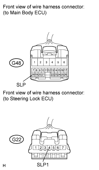
Measure the resistance according to the value(s) in the table below.
Standard Resistance Tester Connection Condition Specified Condition G22-4 (SLP1) - G48-18 (SLP) Always Below 1 Ω G22-4 (SLP1) - Body ground Always 10 kΩ or higher
NG 
REPAIR OR REPLACE HARNESS OR CONNECTOR
OK
PROCEED TO NEXT SUSPECTED AREA SHOWN IN PROBLEM SYMPTOMS TABLE Click here
-