POWER STEERING SYSTEM, Diagnostic DTC:C1551

| DTC Code | DTC Name |
|---|---|
| C1551 | IG Power Supply Voltage Malfunction |
DESCRIPTION
The power steering ECU distinguishes the engine switch status as on (IG) or off through the IG power source circuit.
| DTC No. | DTC Detection Condition | Trouble Area |
|---|---|---|
| C1551 | IG power source circuit malfunction inside ECU |
|
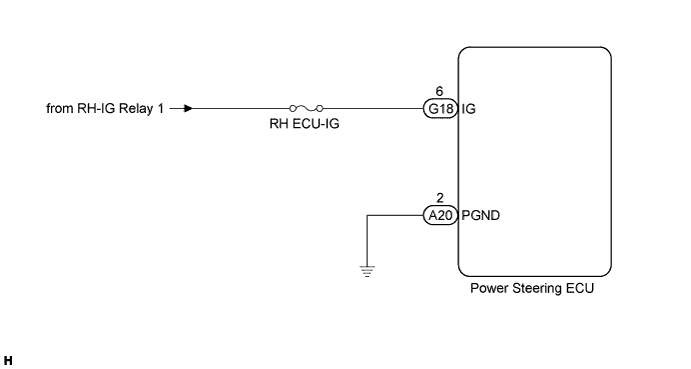
WIRING DIAGRAM
INSPECTION PROCEDURE
Note
If the power steering ECU has been replaced with a new one, perform the rotation angle sensor initialization and torque sensor zero point calibration Click here.
PROCEDURE
-
INSPECT FUSE (RH ECU-IG)
-
Remove the RH ECU-IG fuse from the instrument panel junction block.
-
Measure the resistance according to the value(s) in the table below.
Standard Resistance Fuse Condition Specified Condition RH ECU-IG Always Below 1 Ω
NG 
REPLACE FUSE
OK 
-
-
CHECK HARNESS AND CONNECTOR (BATTERY - POWER STEERING ECU)
-
Disconnect the connectors from the power steering ECU.
-
Measure the voltage according to the value(s) in the table below.
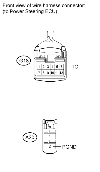
Standard Voltage Tester Connection Switch Condition Specified Condition G18-6 (IG) - Body ground Engine switch on (IG) 11 to 14 V -
Measure the resistance according to the value(s) in the table below.
Standard Resistance Tester Connection Condition Specified Condition A20-2 (PGND) - Body ground Always Below 1 Ω
NG
REPAIR OR REPLACE HARNESS OR CONNECTOR
OK 
REPLACE POWER STEERING ECU Click here
-