PARKING BRAKE PEDAL (for RHD) INSTALLATION

-
INSTALL PARKING BRAKE CONTROL PEDAL ASSEMBLY
-
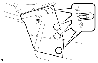
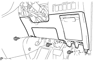
Install the No. 1 parking brake cable assembly to the body with the 2 bolts.
- Torque:
- 8.0 N*m { 82 kgf*cm, 71 in.*lbf }
-

Install the No. 1 parking brake cable assembly with the bolt.
- Torque:
- 8.0 N*m { 82 kgf*cm, 71 in.*lbf }
-
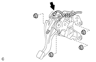
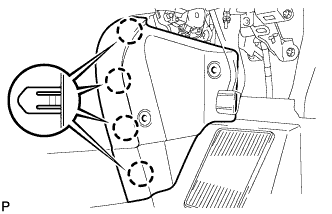
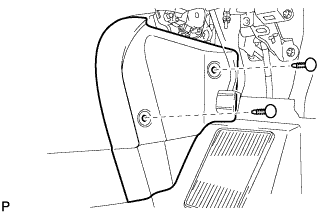
Install the parking brake control pedal assembly to the body with the 4 nuts.
- Torque:
- 13 N*m { 130 kgf*cm, 9 ft.*lbf }
-
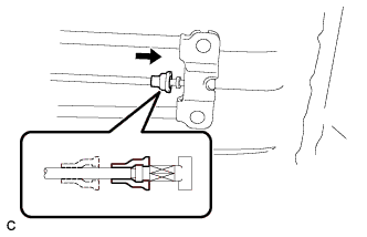
Connect the connector and engage the clamp.
-
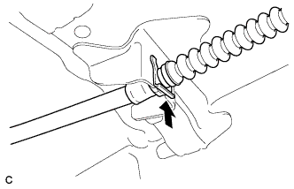
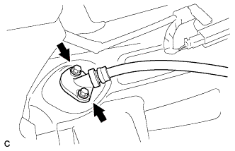
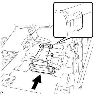
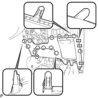
Install the No. 1 parking brake cable assembly to the body with a new clip.
-
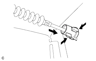
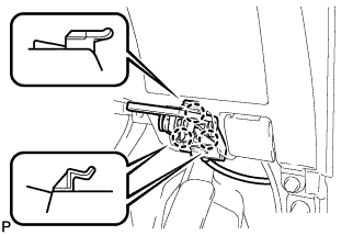
Engage the 2 claws to install the parking brake cable inner guide to the body.
-
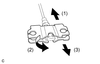
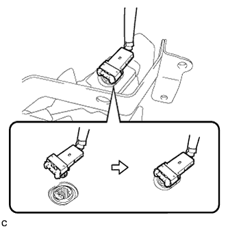
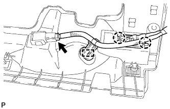
Connect the No. 1 parking brake cable assembly to the parking brake cable equalizer in the order shown in the illustration.
-
Engage the boot of the No. 1 parking brake cable assembly as shown in the illustration.
-
-
INSTALL FRONT FLOOR MAT PAD
-
Install the front floor mat pad.
-
Install the floor carpet to the original position.
-
-
INSTALL REAR NO. 1 AIR DUCT
-
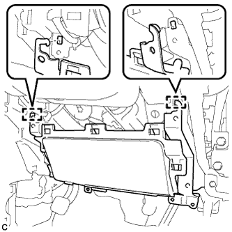
Engage the 2 claws to install the rear No. 1 air duct.
-
-
INSTALL REAR NO. 2 AIR DUCT
-
Engage the 2 claws to install the rear No. 2 air duct.
-
Install the clip.
-
-
INSTALL DASH PANEL INSULATOR PAD RH
-
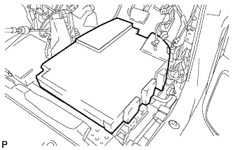
Install the dash panel insulator pad RH.
-
-
INSTALL DRIVER SIDE KNEE AIRBAG ASSEMBLY
-
Check that the engine switch is off.
-
Check that the cable is disconnected from the negative (-) battery terminal.
CAUTION:
Wait at least 90 seconds after disconnecting the cable from the negative (-) battery terminal to disable the SRS system.
-
Connect the connector to the driver side knee airbag assembly.
Note
When connecting the airbag connector, take care not to damage the airbag wire harness.
-
Engage the 2 hooks and temporarily install the driver side knee airbag assembly.
-
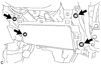
Install the driver side knee airbag assembly with the 4 bolts firmly.
- Torque:
- 10 N*m { 102 kgf*cm, 7 ft.*lbf }
-
-
INSTALL INSTRUMENT CLUSTER FINISH PANEL ASSEMBLY
-
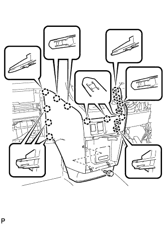
Engage the 15 claws.
Tech Tips
Before engaging the 15 claws, make sure that the claws are positioned correctly.
Note
Make sure that the claws are fully engaged.
-
Install the instrument cluster finish panel assembly with the bolt <C>.
-
-
INSTALL INSTRUMENT PANEL BOX ASSEMBLY
-
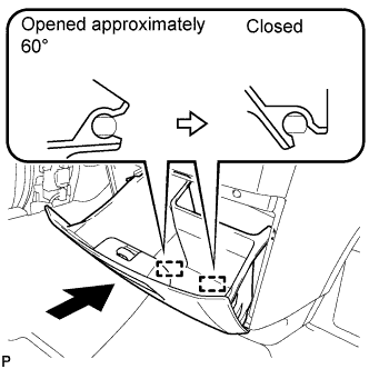
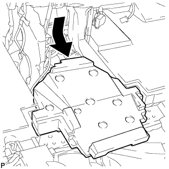
With the instrument panel box assembly opened approximately 60° from its closed position, engage the 2 hinges horizontally.
Note
Engaging the hinges from the top will deform the hinges. Be sure to install the instrument panel box assembly horizontally.
-
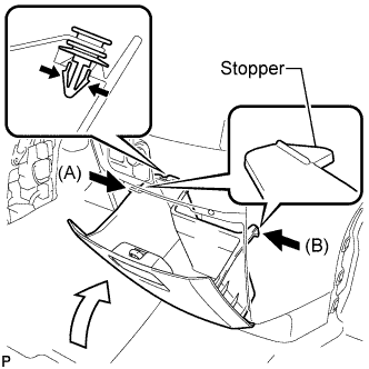
Install the damper clip.
-
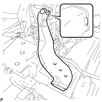
Slightly bend stoppers (A) and (B) in the directions indicated by the arrows in the illustration and engage the stoppers to install the instrument panel box assembly.
-
-
INSTALL CENTER FLOOR CARPET COVER LH
-
Engage the 4 claws.
-

Install the center floor carpet cover LH with the clip.
-
-
INSTALL CENTER FLOOR CARPET COVER RH
-
Engage the 4 claws.
-
Install the center floor carpet cover RH with the 2 clips.
-
-
INSTALL LOWER INSTRUMENT PANEL FINISH PANEL
-
Engage the 3 guides and 14 claws.
Tech Tips
Make sure that all claws around the entire circumference of the driver side knee airbag assembly are fully engaged.
Note
Make sure that the claws are fully engaged.
-
Install the lower instrument panel finish panel with the 3 screws <B>.
-

Engage the 3 claws and the fuel lid lock control cable assembly.
-
Engage the 3 claws and the hood lock control cable assembly.
-
-
INSTALL NO. 1 INSTRUMENT PANEL UNDER COVER SUB-ASSEMBLY
-
Engage the 2 claws and DLC3.
-
Engage the clamp.
-
Connect the connector.
-

Engage the 2 claws and 2 guides.
Note
Make sure that the claws are fully engaged.
-
Install the No. 1 instrument panel under cover sub-assembly with the 2 screws <B>.
-
-
INSTALL FRONT SEAT ASSEMBLY (for RH Side)
-
for Manual Seat: Click here
-
for Power Seat: Click here
-
-
INSTALL FRONT SEAT ASSEMBLY (for LH Side)
-
for Manual Seat: Click here
-
for Power Seat: Click here
-
-
ADJUST PARKING BRAKE
-
Remove the rear wheel.
-
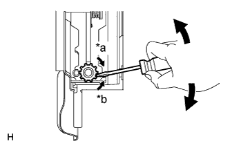
Text in Illustration *a Contract *b Expand Remove the parking brake shoe adjusting hole plug, and turn the adjuster to expand the shoe adjuster until the rear disc locks.
-
Turn and contract the shoe adjuster until the rear disc can rotate smoothly.
Standard return notches 8 notches -
Install the rear wheel.
- Torque:
- 103 N*m { 1050 kgf*cm, 76 ft.*lbf }
-
Remove the No. 1 instrument panel under cover sub-assembly.
-
for RHD: Click here
-
for LHD: Click here
-
-
Completely release the parking brake pedal.
-
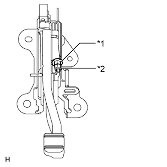
Text in Illustration *1 No. 1 Wire Adjusting Nut *2 Lock Nut Loosen the lock nut and turn the No. 1 wire adjusting nut until the pedal travel is correct.
Parking Brake Pedal Travel at 300 N (31 kgf, 67.5 lbf) Specification for LHD 5 to 7 clicks for RHD 4 to 6 clicks -
Tighten the lock nut.
- Torque:
- 7.0 N*m { 71 kgf*cm, 62 in.*lbf }
-
Count the number of clicks after depressing and releasing the parking brake pedal 3 or 4 times.
Parking Brake Pedal Travel at 300 N (31 kgf, 67.5 lbf) Model Specification for LHD 5 to 7 clicks for RHD 4 to 6 clicks -
Install the No. 1 instrument panel under cover sub-assembly.
-
for RHD: Click here
-
for LHD: Click here
-
-
Check that the parking brake shoe has no brake drag.
-