STEERING LOCK SYSTEM DIAGNOSIS SYSTEM

-
DESCRIPTION
-
DIAGNOSTIC SYSTEM
When troubleshooting a vehicle with a diagnostic system, the only difference from the usual troubleshooting procedure is connecting the intelligent tester to the vehicle and reading various data output from the vehicle's steering lock ECU.
The steering lock ECU records DTCs when the ECU detects a malfunction in the ECU itself or in system circuits.
To check the DTCs, connect the intelligent tester to the DLC3 on the vehicle. The intelligent tester enables the DTCs to be cleared, the indicators to be activated, and the Data List to be checked.
-
The steering lock ECU diagnosis information cannot be read directly from the steering lock ECU by the tester. The diagnosis information from the steering lock ECU is transmitted to the tester via the certification ECU (smart key ECU assembly) using the Controller Area Network (CAN).
-
-
CHECK DLC3
-
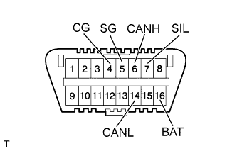
The ECU uses ISO 15765-4 for communication. The terminal arrangement of the DLC3 complies with ISO 15031-3 and matches the ISO 15765-4 format.
-
Symbol (Terminal No.) Terminal Description Condition Specified Condition SIL (7) - SG (5) Bus "+" line During communication Pulse generation CG (4) - Body ground Chassis ground Always Below 1 Ω SG (5) - Body ground Signal ground Always Below 1 Ω BAT (16) - Body ground Battery positive Always 11 to 14 V CANH (6) - CANL (14) CAN bus line Engine switch off* 54 to 67 Ω CANH (6) - CG (4) HIGH-level CAN bus line Engine switch off* 200 Ω or higher CANL (14) - CG (4) LOW-level CAN bus line Engine switch off* 200 Ω or higher CANH (6) - BAT (16) HIGH-level CAN bus line Engine switch off* 6 kΩ or higher CANL (14) - BAT (16) LOW-level CAN bus line Engine switch off* 6 kΩ or higher Note
*: Before measuring the resistance, leave the vehicle as is for at least 1 minute and do not operate the engine switch, any other switches or the doors.
Tech Tips
If the display shows a communication error message after connecting the intelligent tester to the DLC3 and turning the engine switch on (IG), there is a problem either with the vehicle or the intelligent tester.
-
If communication is normal when connecting the intelligent tester to another vehicle, inspect the DLC3 on the original vehicle.
-
If communication is still not possible when connecting the intelligent tester to another vehicle, the problem is probably in the intelligent tester itself. Consult the Service Department listed in the intelligent tester operator's manual.
-
-
-
-
WARNING FUNCTION OF ENGINE SWITCH INDICATOR
-
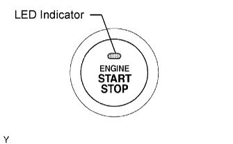
The steering lock ECU blinks the LED indicator of the engine switch when any of the following problems occurs in the system:
Detection Item Indicator Light Blink Pattern Indication Status Countermeasure Steering lock is still not released
-
Blinks in green at 1-second intervals
-
Goes off 15 seconds after blinking starts
The motor operates to release the steering lock, but the steering lock cannot be released (e.g. the lock bar is stuck in the steering column). Push the engine switch while turning the steering wheel left or right. Malfunction in smart entry and start system
-
Blinks in amber at 2-second intervals
-
Goes off 15 seconds after the engine switch is turned off while blinking
-
There is a short in the devices activating the motor.
-
There is a problem in the steering lock ECU or main body ECU.
Troubleshoot by following How to Proceed with Troubleshooting Click here.
-
-
-
WARNING FUNCTION OF COMBINATION METER
-
The steering lock ECU displays a warning on the combination meter if any of the following problems occurs in the system:
Detection Item Display Indication Status Countermeasure Steering lock is still not released "Steering Lock is still active" The motor operates to release the steering lock, but the steering lock cannot be released (e.g. the lock bar is stuck in the steering column). Push the engine switch while turning the steering wheel left or right. Malfunction in smart entry and start system "Check Steering Lock System"
-
There is a short in the devices activating the motor.
-
There is a problem in the steering lock ECU or main body ECU.
Troubleshoot by following How to Proceed with Troubleshooting Click here.
-
-