BRAKE BOOSTER INSTALLATION

-
INSTALL BRAKE BOOSTER GASKET
-
Install a new brake booster gasket to the brake booster assembly.
-
-
INSTALL BRAKE BOOSTER ASSEMBLY (for LHD)
-
If installing a new brake booster assembly, cover the threads on the push rod of the brake booster assembly with protective tape.
-
Install the brake booster assembly to the vehicle body.
Note
Do not apply excessive force to the brake lines.
-
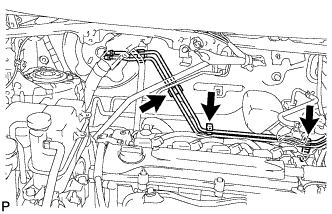
Install the brake line to the body with the bolt.
- Torque:
- 8.0 N*m { 82 kgf*cm, 71 in.*lbf }
-
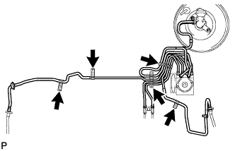
Engage the 5 clamps.
Note
Be careful not to damage the brake lines or clamps. If any parts are damaged, replace them with new ones.
-
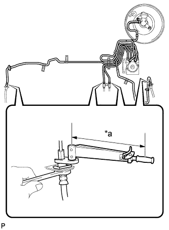
Text in Illustration *a Fulcrum Length Using a union nut wrench (10 mm), connect the 4 brake lines.
- Torque:
- without union nut wrench
- 15 N*m { 155 kgf*cm, 11 ft.*lbf }
- with union nut wrench
- 14 N*m { 143 kgf*cm, 10 ft.*lbf }
Note
-
Use a torque wrench with a fulcrum length of 250 mm (9.84 in.).
-
This torque value is effective when the union nut wrench is parallel to the torque wrench.
-
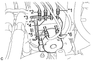
Text in Illustration *1 To front wheel cylinder RH *2 To front wheel cylinder LH *3 To rear wheel cylinder RH *4 To rear wheel cylinder LH *5 From 2nd brake line of master cylinder *6 From 1st brake line of master cylinder Temporarily tighten each brake line to the correct positions of the brake actuator assembly with bracket as shown in the illustration.
-
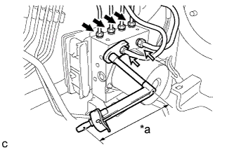
Text in Illustration *a Fulcrum Length 
Use Union Nut Wrench 10 mm 
Use Union Nut Wrench 12 mm Using a union nut wrench (10 mm) and a union nut wrench (12 mm), connect the 6 brake lines to the brake actuator.
- Torque:
- Flare nut (M10) without a union nut wrench (10 mm)
- 15 N*m { 155 kgf*cm, 11 ft.*lbf }
- Flare nut (M10) with a union nut wrench (10 mm)
- 14 N*m { 143 kgf*cm, 10 ft.*lbf }
- Flare nut (M12) without a union nut wrench (12mm)
- 20 N*m { 199 kgf*cm, 14 ft.*lbf }
- Flare nut (M12) with a union nut wrench (12mm)
- 18 N*m { 183 kgf*cm, 13 ft.*lbf }
Note
-
Use a torque wrench with a fulcrum length of 250 mm (9.84 in.).
-
This torque value is effective when the union nut wrench is parallel to the torque wrench.
-
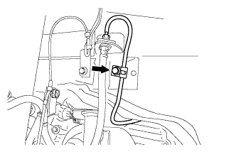
Connect the vacuum hose to the brake booster assembly and move the clamp back into position.
-
Remove the protective tape from the threads of the brake booster assembly push rod.
-
-
INSTALL BRAKE BOOSTER ASSEMBLY (for RHD)
-
If installing a new brake booster assembly, cover the threads on the push rod of the brake booster assembly with protective tape.
-
Install the brake booster assembly to the vehicle body.
Note
Do not apply excessive force to the brake lines.
-
Engage the 3 clamps and move the brake lines back into position.
Note
Be careful not to damage the brake lines or clamps. If any parts are damaged, replace them with new ones.
-
Connect the vacuum hose to the brake booster assembly and move the clamp back into position.
-
Remove the protective tape from the threads of the brake booster assembly push rod.
-
-
INSTALL BRAKE MASTER CYLINDER PUSH ROD CLEVIS
-
Temporarily install the brake master cylinder push rod clevis with the lock nut.
Tech Tips
The lock nut will be fully tightened when the Inspect and Adjust Brake Pedal Height procedure is performed Click here.
-
-
INSTALL BRAKE PEDAL SUPPORT ASSEMBLY
Tech Tips
Refer to the instructions for installation of the brake pedal support assembly Click here.