VEHICLE STABILITY CONTROL SYSTEM, Diagnostic DTC:C0365/28, C1234/34

| DTC Code | DTC Name |
|---|---|
| C0365/28 | Malfunction in Deceleration Sensor |
| C1234/34 | Yaw Rate Sensor Malfunction |
DESCRIPTION
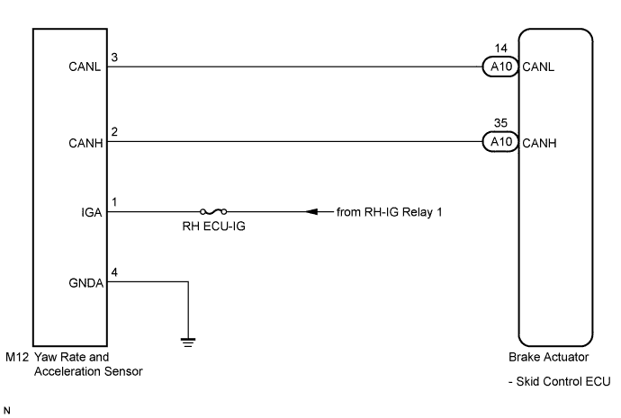
The skid control ECU receives signals from the yaw rate and acceleration sensor via the CAN communication system.
The yaw rate sensor has a built-in acceleration sensor.
If there is trouble in the bus lines between the yaw rate and acceleration sensor and the CAN communication system, DTC U0123/62 (malfunction in CAN communication with the yaw rate sensor) is output.
| DTC No. | DTC Detection Condition | Trouble Area |
|---|---|---|
| C0365/28 | When any of the following is detected:
|
|
| C1234/34 | Sensor malfunction signal is received from the yaw rate sensor. |
|
WIRING DIAGRAM
INSPECTION PROCEDURE
Tech Tips
When U0123/62 and/or U0126/63 is output together with C0365/28 and/or C1234/34, inspect and repair the trouble areas indicated by U0123/62 and/or U0126/63 first Click here.
PROCEDURE
-
CHECK DTC
-
Clear the DTC Click here.
-
Start the engine.
-
At a speed of 30 km/h (18 mph) or more, drive the vehicle, turn the steering wheel, and decelerate (depress the brake pedal) the vehicle.
-
Turn the engine switch on (IG) again and check that no CAN communication system DTC is output Click here.
Result Result Proceed to CAN communication system DTC is not output A CAN communication system DTC is output B
B 
INSPECT CAN COMMUNICATION SYSTEM Click here
A 
-
-
CHECK YAW RATE AND ACCELERATION SENSOR INSTALLATION
-
Turn the engine switch off.
-
Check that the yaw rate and acceleration sensor has been installed properly Click here.
OK The sensor should be tightened to the specified torque. The sensor should not be tilted.
NG
INSTALL YAW RATE AND ACCELERATION SENSOR CORRECTLY Click here
OK
-
-
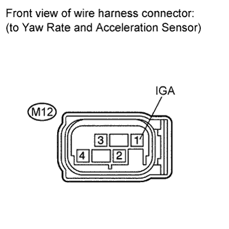
INSPECT YAW RATE AND ACCELERATION SENSOR (IGA TERMINAL)
-
Disconnect the yaw rate and acceleration sensor connector.
-
Turn the engine switch on (IG).
-
Measure the voltage according to the value(s) in the table below.
Standard Voltage Tester Connection Switch Condition Specified Condition M12-1 (IGA) - Body ground Engine switch on (IG) 11 to 14 V
NG
REPAIR OR REPLACE HARNESS OR CONNECTOR (IGA CIRCUIT)
OK
-
-
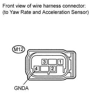
INSPECT YAW RATE AND ACCELERATION SENSOR (GNDA TERMINAL)
-
Turn the engine switch off.
-
Measure the resistance according to the value(s) in the table below.
Standard Resistance Tester Connection Condition Specified Condition M12-4 (GNDA) - Body ground Always Below 1 Ω Tech Tips
If troubleshooting has been carried out according to the Problem Symptoms Table, refer back to the table and proceed to the next step Click here.
NG
REPAIR OR REPLACE HARNESS OR CONNECTOR (GNDA CIRCUIT)
OK 
REPLACE YAW RATE AND ACCELERATION SENSOR Click here
-