VEHICLE STABILITY CONTROL SYSTEM TERMINALS OF ECU

-
TERMINALS OF ECU
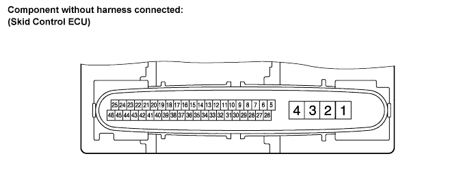
Terminal No. (Symbol) Terminal Description 1 (GND2) Pump motor ground 2 (+BM) Motor relay power supply 3 (+BS) Solenoid relay power supply 4 (GND1) Skid control ECU ground 5 (FL-) Front wheel speed LH (-) signal input 6 (RL+) Rear wheel speed LH (+) signal input 8 (RR+) Rear wheel speed RH (+) signal input 9 (FR+) Front wheel speed RH (+) signal input 10 (FR-) Front wheel speed RH (-) signal input 11 (D/G) Diagnosis tester communication line 14 (CANL) CAN communication line L 16 (TS) Sensor check input 17 (CSW) VSC OFF switch input 20 (FSW+) Brake pedal load sensing switch input 26 (FL+) Front wheel speed LH (+) signal input 27 (RL-) Rear wheel speed LH (-) signal input 28 (IG1) ECU power supply 29 (RR-) Rear wheel speed RH (-) signal input 30 (STP) Stop light switch input 33 (SP1) Speed signal output for speedometer 35 (CANH) CAN communication line H 42 (BZ) Skid control buzzer output -
TERMINAL INSPECTION
-
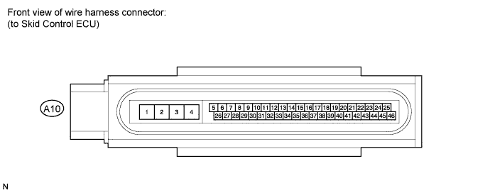
Disconnect the connector and measure the voltage and resistance on the wire harness side.
Tech Tips
Voltage cannot be measured with the connector connected to the skid control ECU because the connector is watertight.
Standard Terminal No. (Symbol) Wiring Color Terminal Description Condition Specified Condition A10-1 (GND2) - Body ground W-B - Body ground Pump motor ground Always Below 1 Ω A10-2 (+BM) - Body ground Y - Body ground Motor relay power supply Always 11 to 14 V A10-3 (+BS) - Body ground P - Body ground Solenoid relay power supply Always 11 to 14 V A10-4 (GND1) - Body ground W-B - Body ground Skid control ECU ground Always Below 1 Ω A10-17 (CSW) - Body ground R - Body ground VSC OFF switch input VSC OFF switch held ON → OFF (Not pressed) Below 1 Ω → 10 kΩ or higher A10-28 (IG1) - Body ground BR - Body ground ECU power supply Engine switch on (IG) 11 to 14 V A10-30 (STP) - Body ground Y - Body ground Stop light switch input Stop light switch ON → OFF (Brake pedal depressed → released) 8 to 14 V → Below 1.5 V
-