- Click here
REMOVE REAR WHEELS
- Click here
REMOVE TAIL EXHAUST PIPE ASSEMBLY
for 2AZ-FE: (Click here)
for 2GR-FE: (Click here)
- Click here
SEPARATE REAR SPEED SENSOR WIRE (for LH Side)
-
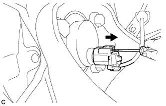
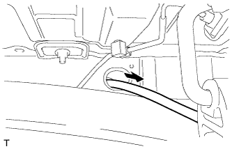
Using a screwdriver, disconnect the rear speed sensor wire from the rear axle hub and bearing assembly LH.
Note:Be careful not to damage the rear speed sensor.
-
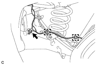
Remove the bolt and disengage the 2 clamps.
-
Separate the rear speed sensor wire from the rear axle beam assembly.
-
- Click here
SEPARATE REAR SPEED SENSOR WIRE (for RH Side)
Tip:Perform the same procedure as the LH side.
- Click here
REMOVE REAR COIL SPRING LH
-
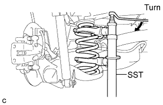
Install SST to the rear coil spring so that the upper and lower hooks of SST are as far apart as possible.
09727-30021 -
Using SST, compress the rear coil spring until it moves freely.
09727-30021 Note:Do not use an impact wrench. It will damage SST.
-
Remove the rear coil spring with SST from the vehicle.
09727-30021 -
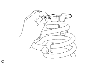
Remove the rear upper coil spring insulator from the rear coil spring.
-
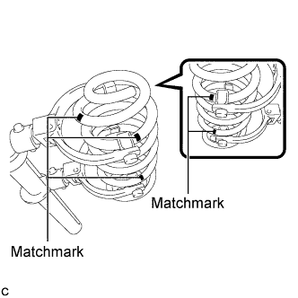
Put matchmarks on the rear coil spring as shown in the illustration.
Tip:Put 4 matchmarks on the spring to show the position of the ends of the SST hooks and put 1 matchmark on the spring to show the mounting side of SST.
-
Release SST and remove it from the rear coil spring.
09727-30021 Note:Do not use an impact wrench. It will damage SST.
-
- Click here
REMOVE REAR COIL SPRING RH
Tip:Perform the same procedure as the LH side.
- Click here
REMOVE REAR LOWER COIL SPRING INSULATOR LH
-
Remove the rear lower coil spring insulator from the rear axle beam assembly.
-
- Click here
REMOVE REAR LOWER COIL SPRING INSULATOR RH
Tip:Perform the same procedure as the LH side.
- Click here
DRAIN BRAKE FLUID
Note:If brake fluid leaks onto any painted surface, immediately wash it off.
- Click here
REMOVE REAR DISC BRAKE CALIPER ASSEMBLY LH
-
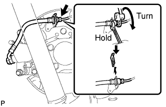
Using a union nut wrench (10 mm), disconnect the rear No. 4 brake tube while holding the rear flexible hose LH with a wrench.
Note:
-
Do not kink or damage the brake line.
-
Do not allow any foreign matter such as dirt and dust to enter the brake line.
-
-
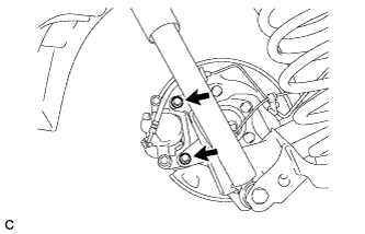
Remove the 2 bolts and separate the rear disc brake caliper assembly with rear flexible hose LH from the backing plate.
-
- Click here
REMOVE REAR DISC BRAKE CALIPER ASSEMBLY RH
Tip:Perform the same procedure as the LH side.
- Click here
REMOVE PARKING BRAKE SHOE ADJUSTING HOLE PLUG
-
Remove the 2 parking brake shoe adjusting hole plugs from the 2 rear discs.
-
- Click here
REMOVE REAR DISC
-
Remove the 2 rear discs (Click here).
-
- Click here
REMOVE REAR NO. 4 BRAKE TUBE
-
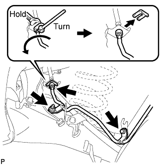
Using a union nut wrench (10 mm), disconnect the rear No. 4 brake tube while holding the rear brake tube flexible hose with a wrench.
Note:
-
Do not kink or damage the brake line.
-
Do not allow any foreign matter such as dirt and dust to enter the brake line.
-
-
Remove the clip, bolt, nut and rear No. 4 brake tube from the rear axle beam assembly.
-
- Click here
REMOVE REAR NO. 3 BRAKE TUBE
-
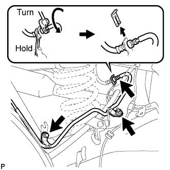
Using a union nut wrench (10 mm), disconnect the rear No. 3 brake tube while holding the rear brake tube flexible hose with a wrench.
Note:
-
Do not kink or damage the brake line.
-
Do not allow any foreign matter such as dirt and dust to enter the brake line.
-
-
Remove the clip, bolt, nut and rear No. 3 brake tube from the rear axle beam assembly.
-
- Click here
SEPARATE NO. 3 PARKING BRAKE CABLE ASSEMBLY
-
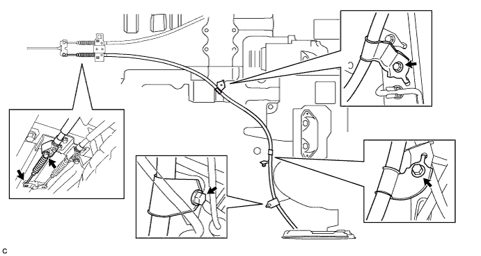
Remove the 4 bolts and separate the No. 3 parking brake cable assembly from the body.
-
Separate the No. 3 parking brake cable assembly from the parking brake equalizer.
-
- Click here
SEPARATE NO. 2 PARKING BRAKE CABLE ASSEMBLY
-
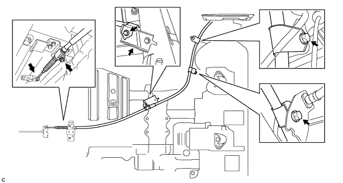
Remove the 4 bolts and separate the No. 2 parking brake cable assembly from the body.
-
Separate the No. 2 parking brake cable assembly from the parking brake equalizer.
-
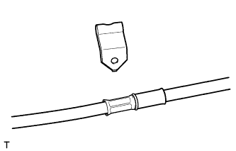
Remove the No. 1 parking brake cable clamp from the No. 2 parking brake cable assembly.
-
Remove the No. 2 parking brake cable assembly through the body hole.
-
- Click here
REMOVE REAR AXLE HUB AND BEARING ASSEMBLY LH
-
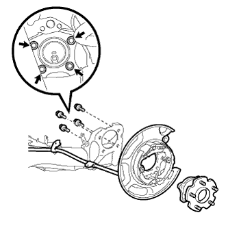
Remove the 4 bolts and then remove the rear axle hub and bearing assembly LH from the rear axle beam assembly while supporting the parking brake assembly LH.
Note:Do not drop the parking brake assembly LH.
-
Remove the parking brake assembly LH together with the No. 3 parking brake cable assembly from the vehicle.
-
- Click here
REMOVE REAR AXLE HUB AND BEARING ASSEMBLY RH
Tip:Perform the same procedure as the LH side.
- Click here
REMOVE REAR HEIGHT CONTROL SENSOR SUB-ASSEMBLY
-
Disconnect the connector.
-
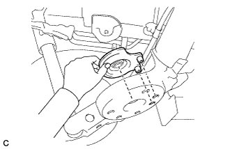
Remove the 4 bolts and rear height control sensor sub-assembly.
-
- Click here
REMOVE REAR AXLE BEAM ASSEMBLY
-
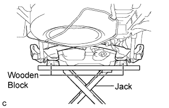
Support the rear axle beam assembly using a jack and 2 wooden blocks as shown in the illustration.
Note:Make sure to secure the rear axle beam assembly to prevent it from dropping.
-
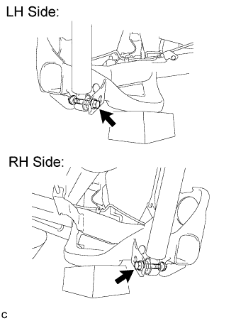
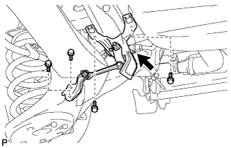
Remove the 2 bolts and 2 nuts, and separate the rear shock absorber assembly from the rear axle beam assembly.
Note:Since stopper nuts are used, loosen the bolts.
-
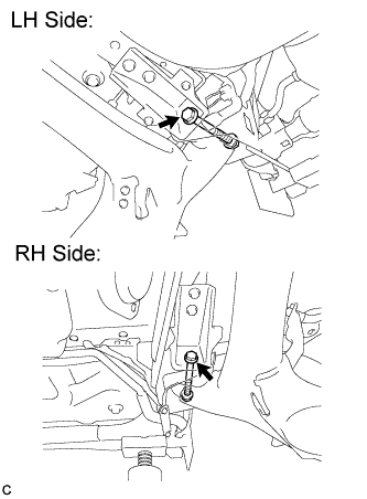
Remove the 2 bolts and 2 nuts, and separate the rear axle beam assembly from the body.
Note:Since stopper nuts are used, loosen the bolts.
-
Lower the rear axle beam assembly and remove it.
-
- Click here
REMOVE REAR AXLE CARRIER BUSHING LH
-
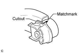
Put a matchmark as shown in the illustration. (Perform this step when reusing the rear axle beam assembly.)
Tip:Put a matchmark on the rear axle beam assembly where it aligns with the bushing cutout.
-
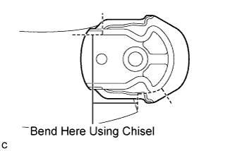
Using a chisel and hammer, bend the 2 portions of the rear axle carrier bushing rib.
Note:Make sure to bend the 2 portions of the bushing rib until the claws of SST (09955-04051) can fit securely.
-
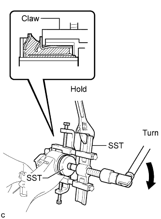
Using SST, remove the rear axle carrier bushing LH from the rear axle beam assembly as shown in the illustration.
09950-40011 09951-04010 09952-04010 09953-04010 09954-04020 09955-04051 09957-04010 09958-04011 09950-60010 09951-00630 Note:
-
Apply a small amount of grease to the threads and tip of SST (center bolt) before use.
-
Set SST to center the bolt in the bushing.
-
When removing the rear axle carrier bushing, do not erase the matchmark on the rear axle beam assembly.
-
If the rear axle beam assembly has been scratched, apply the paint to the rear axle beam assembly.
-
-
- Click here
REMOVE REAR AXLE CARRIER BUSHING RH
Tip:Perform the same procedure as the LH side.