FRONT SUSPENSION MEMBER INSTALLATION

-
INSTALL FRONT SUSPENSION MEMBER BODY MOUNTING REAR CUSHION
-
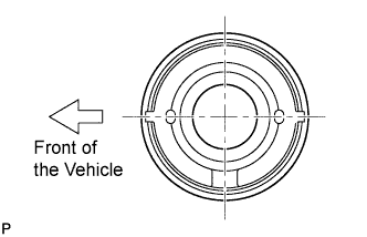
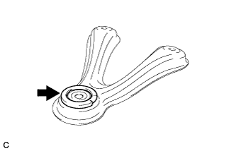
Set a new front suspension member body mounting rear cushion to the front suspension crossmember in the direction shown in the illustration.
-
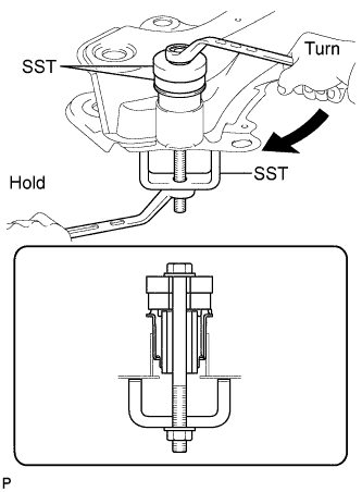
Using SST, press the front suspension member body mounting rear cushion into the front suspension crossmember.
- SST
- 09710-28030 ( 09711-02010, 90101-12177, 90170-12110, 94612-11200 )
- 09950-60010 ( 09951-00600, 09951-00610 )
Tech Tips
Apply grease to the threads of SST.
-
-
INSTALL FRONT SUSPENSION MEMBER BODY MOUNTING FRONT CUSHION
-
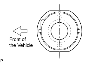
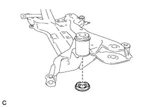
Set a new front suspension member body mounting rear cushion to the front suspension crossmember in the direction shown in the illustration.
-
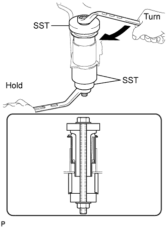
Using SST, press the front suspension member body mounting rear cushion into the front suspension crossmember.
- SST
- 09710-28030 ( 90101-12177, 90170-12110, 94612-11200 )
- 09950-60010 ( 09951-00600, 09951-00440 )
- 09710-30021 ( 09710-03141 )
Tech Tips
Apply grease to the threads of SST.
-
-
INSTALL FRONT SUSPENSION MEMBER BODY MOUNTING REAR STOPPER
-
Install the front suspension member body mounting rear stopper to the front suspension member brace sub-assembly.
-
-
INSTALL FRONT SUSPENSION MEMBER BODY MOUNTING FRONT STOPPER
-
Install the front suspension member body mounting front stopper to the front suspension crossmember sub-assembly.
-
-
INSTALL FRONT SUSPENSION MEMBER DYNAMIC DAMPER (for 2AZ-FE)
-
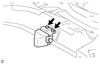
Install the front suspension member dynamic damper with the 2 bolts.
- Torque:
- 32 N*m { 326 kgf*cm, 23 ft.*lbf }
-
-
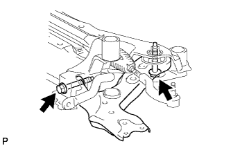
INSTALL STEERING LINK ASSEMBLY
-
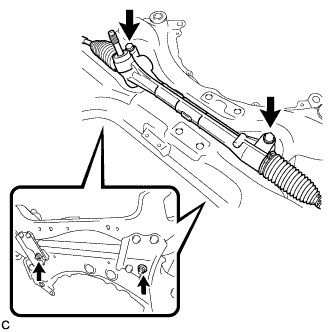
Install the steering link assembly to the front suspension crossmember sub-assembly with the 2 bolts and 2 nuts.
Note
-
Keep the nut from rotating while turning the bolt because the nut has its own stopper.
-
Make sure to tighten the bolts starting from the right side of the vehicle.
- Torque:
- 138 N*m { 1407 kgf*cm, 102 ft.*lbf }
-
-
-
INSTALL FRONT STABILIZER BAR
-
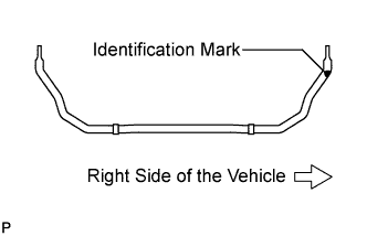
Install the front stabilizer bar to the front suspension crossmember so that the identification mark is positioned on the right side of the vehicle.
-
-
INSTALL FRONT SUSPENSION MEMBER FRONT BRACE LH
-
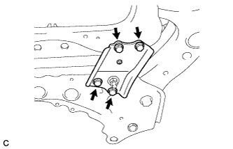
Install the front suspension member front brace LH with the 4 bolts.
- Torque:
- 87 N*m { 887 kgf*cm, 64 ft.*lbf }
Tech Tips
After installing the front suspension member front brace LH, make sure that the protrusion of the No. 1 front stabilizer bar bushing comes out.
-
-
INSTALL FRONT SUSPENSION MEMBER FRONT BRACE RH
Tech Tips
Perform the same procedure as for the LH side.
-
INSTALL FRONT LOWER SUSPENSION ARM SUB-ASSEMBLY LH
-
Temporarily install the front lower suspension arm sub-assembly LH to the front suspension crossmember sub-assembly with the 2 bolts and the nut.
-
Position the front suspension crossmember sub-assembly on a level surface.
-
Using a vernier caliper, measure height *1 and *2.
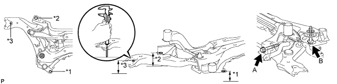
Note
Position the crossmember with the front suspension member braces LH and RH mounted.
-
Check that height *2 is lower than *1 by 10 mm.
-
Position the front lower suspension arm so that height *3 is the same as *1.
-
Tighten the bolt A.
- Torque:
- 233 N*m { 2376 kgf*cm, 172 ft.*lbf }
-
-
INSTALL FRONT LOWER SUSPENSION ARM SUB-ASSEMBLY RH
Tech Tips
Perform the same procedure as for the LH side.
-
INSTALL FRONT SUSPENSION CROSSMEMBER SUB-ASSEMBLY
Tech Tips
Install front suspension crossmember sub-assembly Click here.